General Description
System Description and Operation, AutroSafe Maritime Gas Detection, 116-P-BS420MG/XGB, Rev. E, 2019-12-10,
Autronica Fire and Security
Page 13
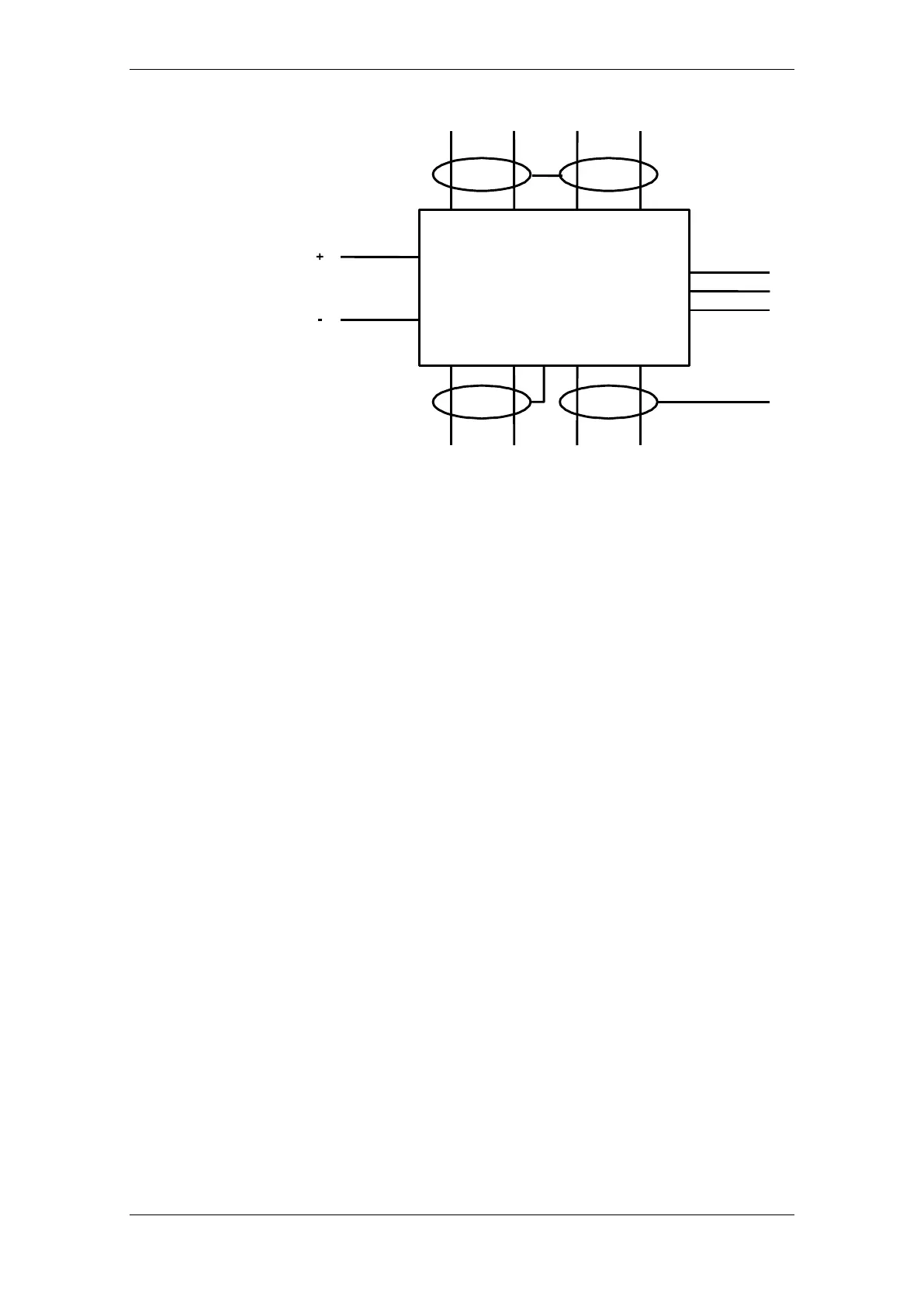
Note: “CT” is used as a reference in case segments of the AFB is left
floating when Boosters or Fibre modems are used. This termination is
normally left open. See “System Shielding and Earthing” in
AutroSafe’s System Description (116-P-ASAFE-SYSTEMD/EGB) for
further directions.
4.8.4 Earthing and Shielding
Shielded cable is required for the AutroFieldBus and PowerLoop, and
the shielding shall be connected to the instrument earth (IE) at one
end of the loop. Any armouring shall be connected to the protective
earth (PE) at multiple points. Refer to AutroSafe’s Installation
Handbook (116-P-ASAFE-INSTALL/DGB) for detailed description of
shielding of cables.
4.8.5 Capacity / Limitations
Generally, the following applies:
Maximum 15 detectors can be connected to each PowerLoop.
May require forced cooling, dissipates up to 30W when fully
loaded.
No branches allowed on PowerLoop or AutroFieldBus.
The total power consumption to PowerLoop units, detectors and cable
loss must be verified by the PowerLoop Calculator (part of the
AutroSafe Configuration Tool).
See also datasheet for BSD-340.

 Loading...