98
COMPACT VOICE ALARM SYSTEM
SERVICE MANUAL
r
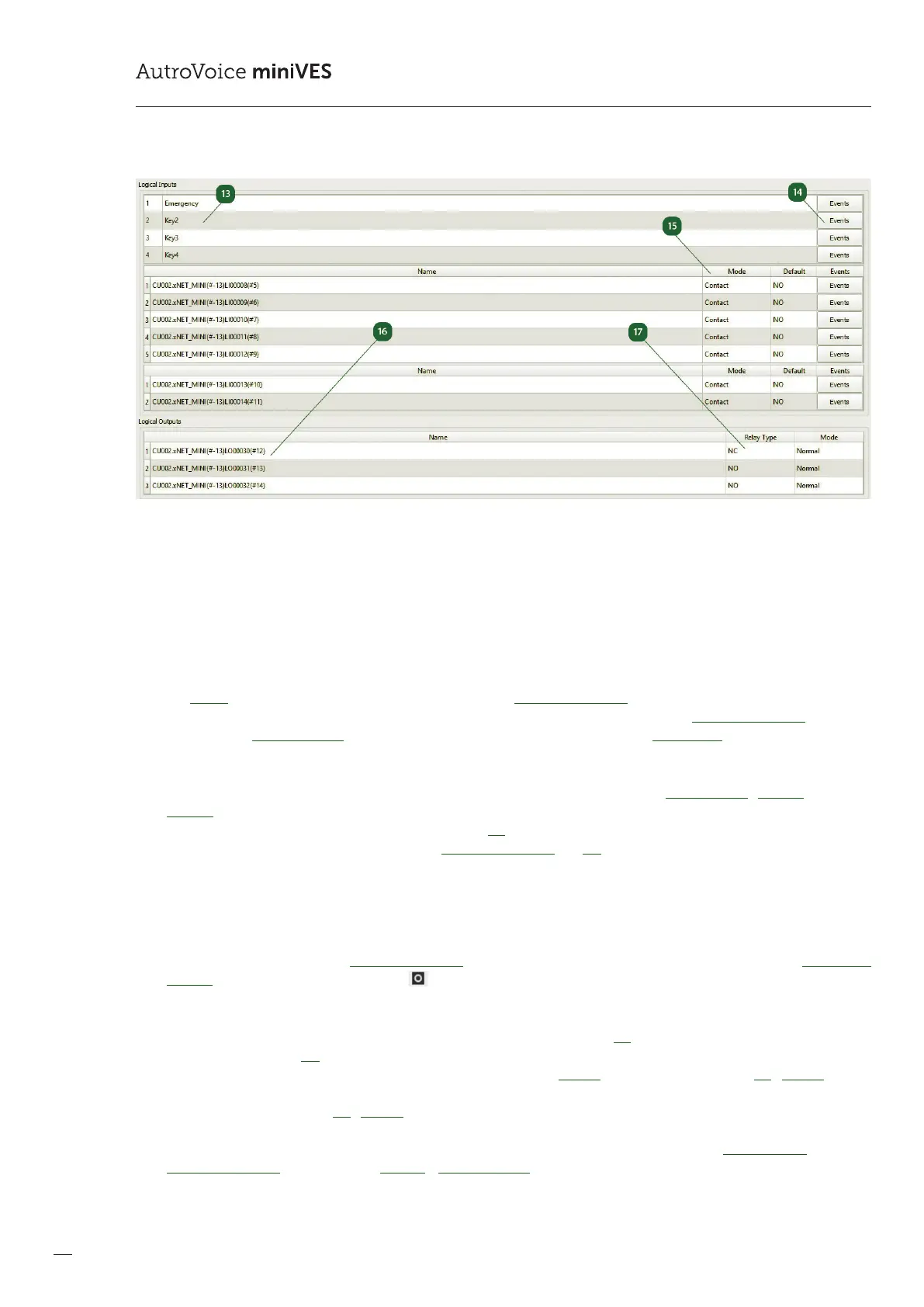
Logical Inputs / buttons
The Logical Inputs tab contains all available buttons as well as logical inputs on the AutroVoice miniVES central unit. Therst
four items in this section are buttons located on the front panel of the AutroVoice miniVES. The next seven inputs are
located on the charger module. Lastly, there are two additional inputs located on the xNet_mini communications card
in the xxxxN series devices. A double click on the name of a button / logical input enables to change the generic name
assigned by the congurator.
t
Logical Inputs / Events
The Events buttons transfers the programmer directly to the EventConguration tab. This enables to assign any function or
event group to a selected button. A right-click on the name of a button / logical input in the EventConguration tab, as well
as selection of Go to denition, enables to return quickly to the editing menu of the Central Unit.
y
Logical Inputs / Mode
The logical input editing window enables activation of the input monitoring function – Mode Contact / Monitor. In case the
Monitor option is selected, it is necessary to install two 4.7 k parametrizing resistors at the end of the line. In the window
Default, we select the input status for inactivity for the NC option the system expects a closed circuit, opening the circuit
results in activation of the function assigned in EventCongifuration. For NO the situation is reverse: the system expects an
open circuit on the input, closing results in activation of the assigned function.
u
Logical Output / Name
The Logical Outputs tab contains all available logical (relay) outputs on the AutroVoice miniVES central unit. A double click
on the name of a logical output enables to change the generic name assigned by the congurator. Assigning a function to
a chosen relay is possible in the EventConguration – select an input event, assign a general function and click Add control
outputs action (the circle in a square icon ).
i
Logical Output / Settings
The relay type window informs about the physical type of the relay installed. NC – normally closed, in case of a power cut,
the relay will be closed, NO – normally open, in case of a power cut, the relay will open. The Mode window enables to reverse
the relay logic, opposite to its behaviour in case of a power cut. The Inverse causes, e.g., that the relay NC / Inverse – in the
original status it is a NO relay, and activation of the function to which it is assigned will change the status of the relay into
the opposite one, i.e. NC. For NC / Normal in the original status (not triggered by any function) the relay is closed, activation
of the function, as assigned to this output, causes that the relay status changes into the opposite one, i.e. open. The values
from the windows Relay Type and Mode are also duplicated in the information window below Scenario State and in the
EventConguration tab the function General – Logical Outputs, also in the information window below State.
 Loading...