Chapter 3 --- Instrument Setup
16
N
ote
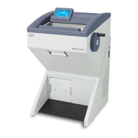
e upper wooden cover now serves as a ramp (fig. 1a.1) on which the QS12 can be moved from the pallet to the oor
by using the handle (g. 1a) (item 2).
• e hinges of the upper wooden cover (g. 1)
(item 1) are inserted into the screws of the
bottom plate (g. 1a) (item 3). e correct
side for this is marked with arrows.
•
e tool (g. 2a) (item 2) for the height
adjustment of the setting feet of the QS12 is
packed together with the accessories of the
QS12 (separate carton on the foot rest of the
QS12).
• Turn the setting feet completely upwards via
this tool so that the QS12 stands with its
rollers on the bottom plate (g 1a) (item
3).
• Via the handle (g 1a) (item 2), roll the QS12
from the bottom plate (g. 1a)(item 3) over
the wooden cover
(g. 1a) (item 1). In doing so, the rear side of
the instrument must face the incline (g. 1a) (
item1).
Fig 1a
e instrument is very heavy. While the instrument rolls down the ramp, it must be carefully controlled.
•
Now the QS12 can be rolled to its site of installation.
• For possible return shipments, please keep all packing materials.
• In the future, if the instrument is transported by forklift, truck, train, ship or aircraft, it must be packed in the
original shipping container with all transportation locks in place.
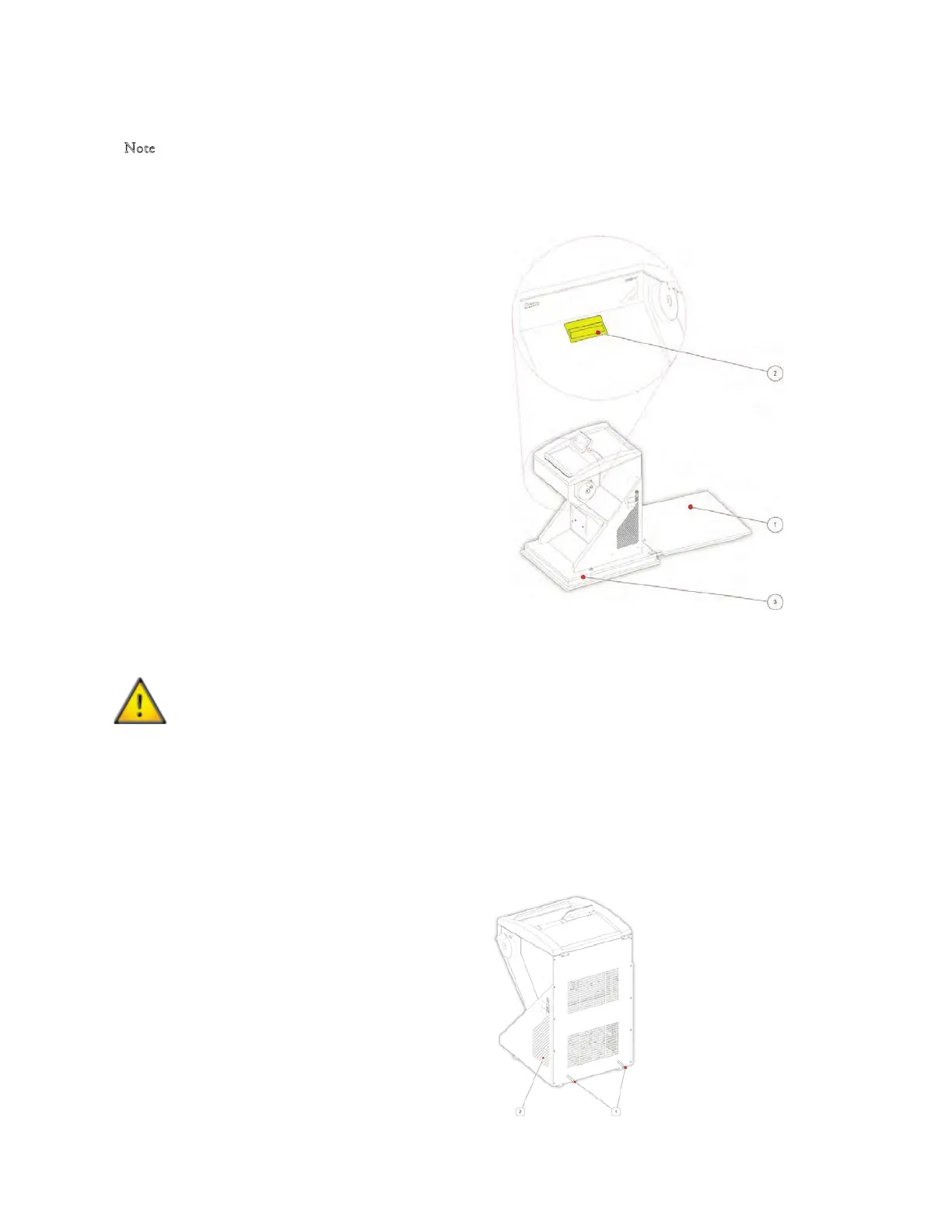
When Unpacking the Instrument, be sure that:
• Enough ventilation for the cooling system is
guaranteed.
• e distance between the wall and rear panel is
approx. 15 cm/ 6”. For this, install the distance
bolts (g 2) (item 1).
• e suction vent areas on either side are kept
free (g. 2) (item 2).
• e mains switch for separating the instrument
from the power supply is accessible at any time.
Fig 2
 Loading...