Chapter 3 --- Instrument Setup
22
If the cutting area of the blade is no longer usable, the blade carrier can be moved:
• e blade itself is clamped solidly into the blade carrier. e complete carrier is moved.
• Open the clamping lever for the carrier and move the carrier to the left or right side.
• Tighten the clamping levers to x this position.
To avoid the danger of injury on the knife during adjustment of specimen, always position the knife
guards over the blade edge.
Fine adjustment of the anti-roll device:
• e ne adjustment of the anti-roll device is carried out via the knurled screw.
Selecting the clearance angle:
• Loosen the
clamping lever.
• Swivel the upper part of the blade carrier on the base until the desired clearance angle is reached.
• e clearance angle can be read on the scale on the left side of the base.
• Bring the clamping lever into clamping position.
• e selected clearance angle is now xed in its position.
N
ote
Usabl
e cuts are only achieved at a clearance angle of 10° or more.
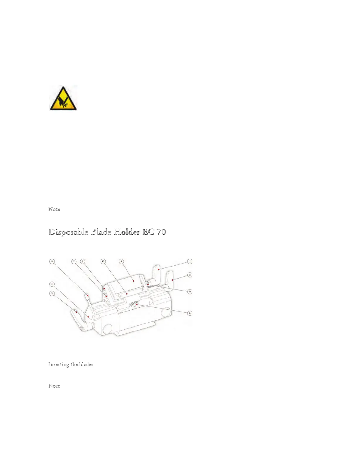
Disposable Blade Holder EC 70
1 Blade Clamping Lever
2 Blade Carrier Clamping Lever
3 Clearance Angle Clamping Lever
4 Clearance Angle Scale
5 Anti-roll Plate Turning Lever
6 Anti-roll Plate Knurling Screw
7 Knurling Screw
8 Spacer strip for high prole blade
9 Clamping Plate
10 Anti-roll Plate
11 Stop Bolt
I
nserting the blade:
• e blade is inserted into the slot behind the cl
amping plate.
N
ote
When
using high prole blades, rst loosen the lever and remove the spacer strip.
• For this, push in the stop bolt and turn clamping lever in a counter clockwise direction over the stop bo
lt.
• Remove the clamping lever together with the eccentric bolt.
• First remove the clamping plate and then the spacer strip (if necessary).