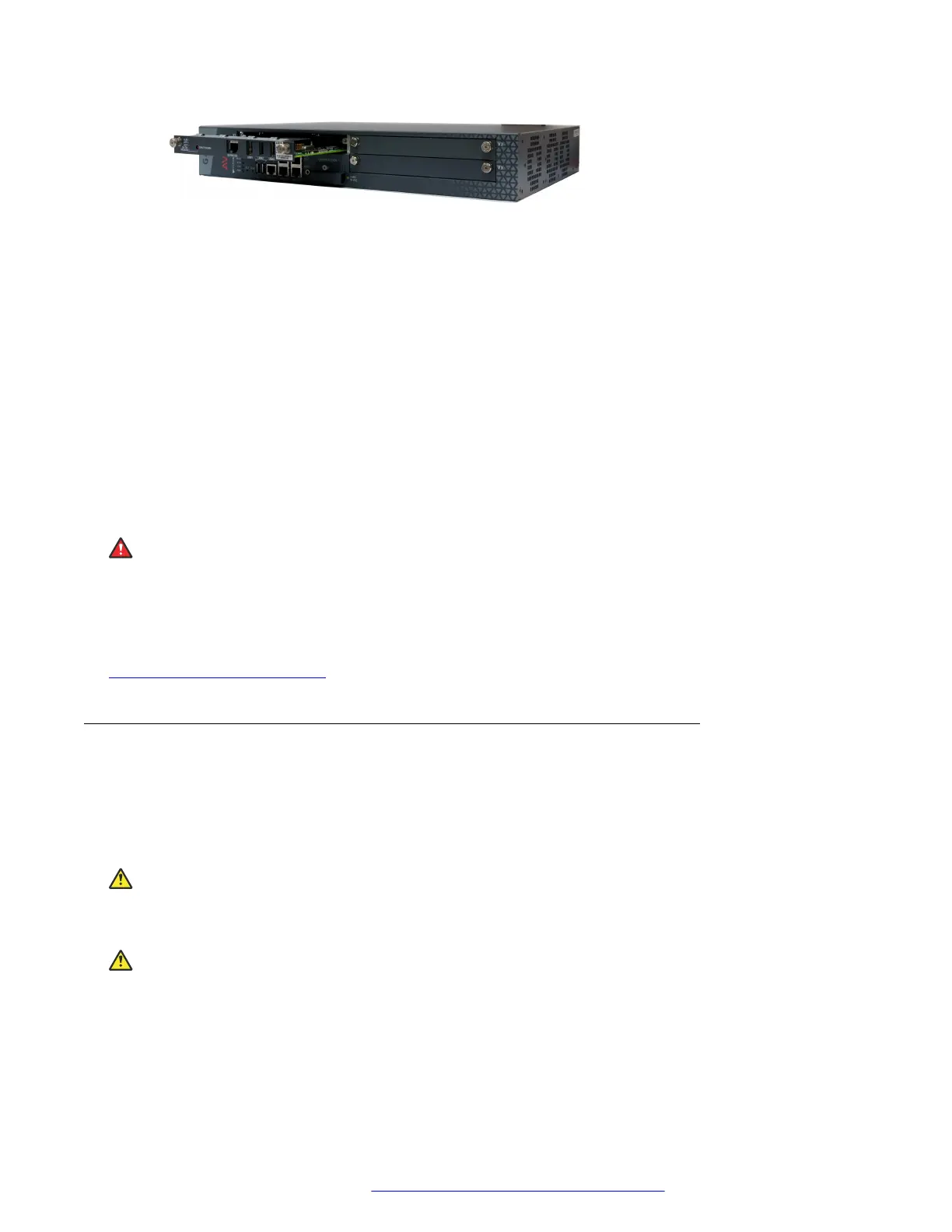
Figure 5: Inserting the S8300 Server
5. Apply firm pressure to engage the connectors.
The connector has pins of different lengths. The long pins engage first to provide grounding.
Medium length and short pins provide power and signal.
6. Lock the S8300 Server module into the chassis by tightening the spring-loaded captive
screws on the front of the module.
If you are installing an S8300, replace the plate labelled “Remove before removing or
inserting S8300 module” above slot V1
7. After you have inserted the S8300 Server module, if applicable, insert the rest of the media
modules.
Make sure to insert each module in a permissible slot.
Result
Danger:
To prevent access to electrical hazards by unauthorized personnel and to ensure continued
compliance to radiated emissions requirements, all captive screws must be securely tightened
such that they cannot be loosened without the use of a tool.
Related links
Installing the media modules on page 28
Inserting media modules
About this task
After you have inserted the S8300 Server module, if applicable, insert the rest of the media
modules. Make sure to insert each module in a permissible slot. Remove the blank plate from the
empty bay.
Electrostatic alert:
Hold media modules only by the edges to avoid damage from static electricity. Do not touch the
top or bottom of the circuit board. If possible, wear a wrist-strap and use an anti-static bag.
Caution:
The connector pins can be bent or damaged if the module is handled roughly, or if misaligned
and then forced into position.
Installing the Branch Gateway and EM200
February 2017 Installation and Upgrades for the Avaya Branch Gateway G430 32
Comments on this document? infodev@avaya.com
 Loading...


