Media module Permitted slots Description
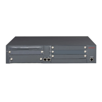
MM712 V1-V3, V5-V8 8 DCP telephone ports
MM714 V1-V3, V5-V8 4 analog telephone ports and 4 analog trunk ports
MM714B V1-V3, V5-V8 4 analog telephone ports, 4 analog trunk ports, and an
emergency transfer relay
MM716 V1-V3, V5-V8 24 analog ports
MM717 V1-V3, V5-V8 24 DCP telephone ports
MM720 V1-V3, V5-V8 8 ISDN BRI trunk or endpoint (telephone or data) ports
MM721 V1-V3, V5-V8 8 ISDN BRI trunk or endpoint (telephone or data) ports
MM722 V1-V3, V5-V8 2 ISDN BRI trunk ports
S8300C or S8300D V1 Communication Manager server
Related links
Installing the media modules on page 28
Inserting the S8300 Server
About this task
You can only install the S8300 in slot V1 on the left side of the Branch Gateway.
Electrostatic alert:
Hold the module only by its edges to avoid damage from static electricity. Do not touch the top
or bottom of the circuit board. If possible, wear a wrist-strap and use an anti-static bag.
Caution:
The connector pins can be bent or damaged if the module is handled roughly, or if misaligned
and then forced into position.
Caution:
Separate ESD paths to the chassis ground connect to the media modules at the spring-loaded
captive screws. Use a screwdriver to ensure the captive screws are securely tightened to
prevent damage to the equipment.
Procedure
1. If you are installing an S8300, remove the plate above slot V1
2. Remove the blank plate from slot V1.
3. Position the server before the V1 bay opening and engage both sides of the module in the
interior guides.
4. Slide the S8300 Server slowly into the chassis, maintaining an even pressure to assure that
the module does not become twisted or disengaged from the guides.
Installing the media modules
February 2017 Installation and Upgrades for the Avaya Branch Gateway G430 31
Comments on this document? infodev@avaya.com


 To Next Page