2 connector on the rear of the G430 are slots V7 and V8.Table 1 on page 31 lists the permitted
slots for each media module.
Allocate a slot for the media module. Make sure your slot allocations allow a permissible slot for
every media module.
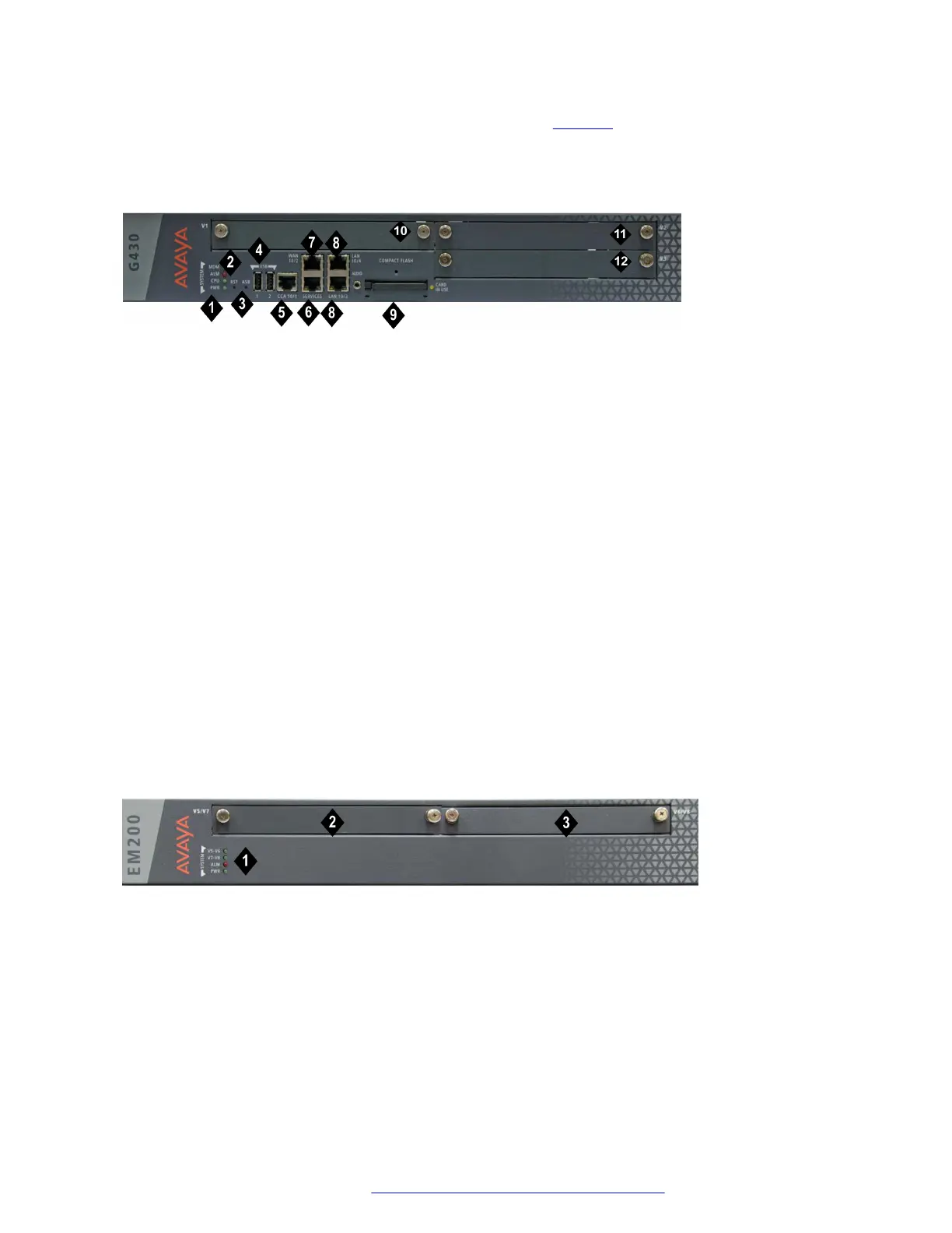
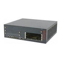
Figure 3: The G430 Branch Gateway front panel ports and slots
Table 1: Figure notes:
1. System LEDs
2. RST button
3. ASB button
4. USB 2.0 ports
5. CCA (Contact Closure) port
6. 10/100M Services port
7. 10/100M ETH WAN port
8. 10/100M ETH LAN ports (10/100/1000 in
G430 hardware vintage 3)
9. Compact Flash slot
10. V1 — slot for media module or S8300
Server
11. V2 — slot for media module
12. V3 — slot for media module
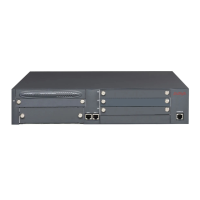
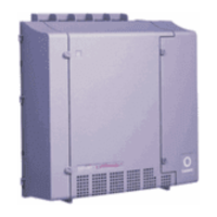
Figure 4: The EM200 front panel slots
Table 2: Figure notes:
1. System LEDs
1. V5/V7 — slot for media module
2. V6/V8 — slot for media module
Installing the Branch Gateway and EM200
July 2018 Deploying and Upgrading Avaya G430 Branch Gateway 30
Comments on this document? infodev@avaya.com


 To Next Page