Caution:
The connector pins can be bent or damaged if the module is handled roughly, or if misaligned
and then forced into position.
Caution:
Separate ESD paths to the chassis ground connect to the media modules at the spring-loaded
captive screws. Use a screwdriver to ensure the captive screws are securely tightened to
prevent damage to the equipment.
Procedure
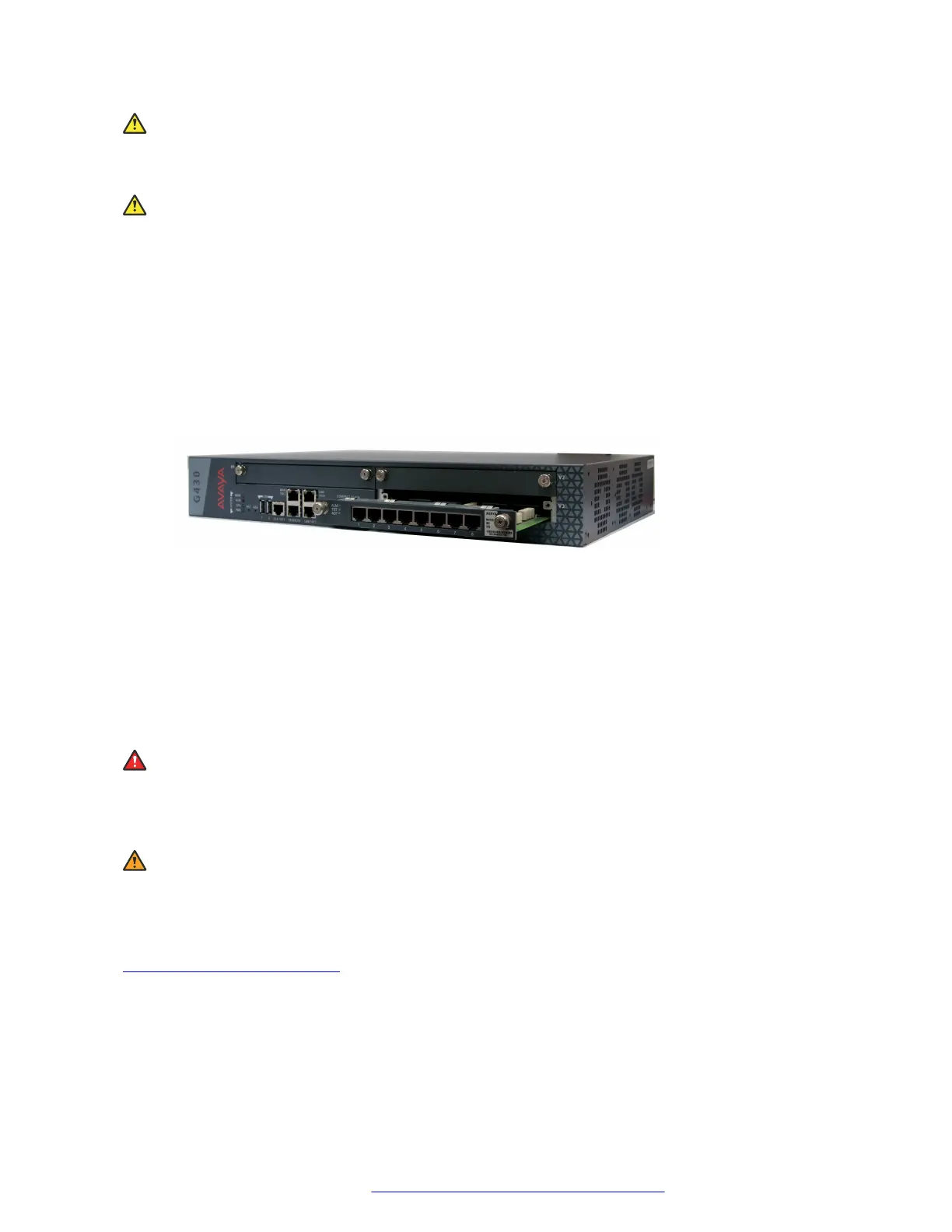
1. Position the media module before the selected bay on the front of the Branch Gateway or
EM200 chassis and engage both sides of the module in the interior guides.
2. Slide the module slowly into the chassis, maintaining an even pressure to assure that the
module does not become twisted or disengaged from the guides.
Figure 6: Inserting a media module
3. Apply firm pressure to engage the connectors.
The media module connector has pins of different lengths. The long pins engage first to
provide grounding. Medium length and short pins provide power and signal.
4. Lock the media module into the chassis by tightening the spring-loaded captive screws on
the front of the module.
Result
Danger:
To prevent access to electrical hazards by unauthorized personnel and to ensure continued
compliance to international radiated emissions requirements, all captive screws must be
securely tightened such that they cannot be loosened without the use of a tool.
Warning:
After you have connected telephones to the various media modules, be sure to add circuit
protection to the lines.
Related links
Installing the media modules on page 28
Installing the media modules
July 2018 Deploying and Upgrading Avaya G430 Branch Gateway 33
Comments on this document? infodev@avaya.com
 Loading...


