Telephones and adjunct systems
368 Installing and Upgrading the Avaya G700 Media Gateway and Avaya S8300 Media Server
To connect the 1152A1 PDU
!
CAUTION:
CAUTION: The 1152A1 PDU has no ON/OFF switch. To connect or disconnect power to the
1152A1 PDU, simply insert or remove the power cable from the AC power
receptacle on the rear of the 1152A1 PDU.
1. Plug a power cord into the power socket on the rear of the 1152A1 Power Distribution Unit.
2. Plug the other end of the power cord into the power receptacle.
The 1152A1 PDU powers up, and the internal fans begin operating.
The 1152A1 PDU then runs through its Power On Self Test (POST), which takes less than
10 seconds. During the test, all the ports on the unit are disabled and the LEDs light up. For
more information on the test, refer to the user’s guide that comes with the unit.
Connecting the 1152A1 PDU cables
All of the ports on the front of the 1152A1 PDU are configured as data route-through ports for all
data wires (pins 1, 2, 3 and 6).
Use a standard CAT5, CAT6 or CAT6e straight-through Ethernet cable (not supplied), including
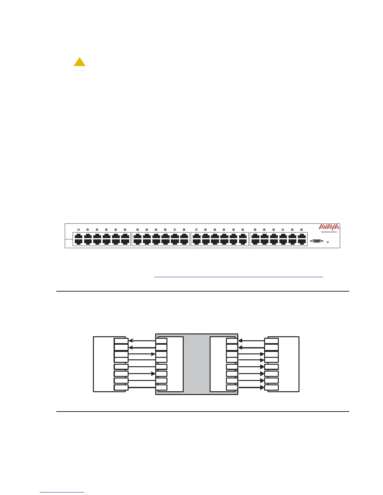
all 8 wires (4 pairs) as shown in Connecting cables to telephones and other end devices
on
page 369.
Figure 28: Connecting telephones and other end devices to the 1152A1 PDU
AC
Console
12
3456
13 14
15 16 17 18
19 20
21 22 23 24
78
9 101112
$3RZHU
'LVWULEXWLRQ8QL
'DWD
3RZHU
'DWD
48Vdc
End Device
1
2
3
4
5
6
7
8
1
2
3
4
5
6
7
8
1
2
3
4
5
6
7
8
1
2
3
4
5
6
7
8
RJ-45 IN RJ-45 OUT
Ethernet
Switch/Hub
5-
5-
data
data
data
DC +
data
DC -
data
data
data
data
spare
spare
spare
spare
Data In
Data & Power Out
DC +
DC -
$3RZHU'LVWULEXWLRQ8QLW