43
Appendix C: Wiring Diagrams and Pin Assignments
LTC IN and OUT XLR Ports
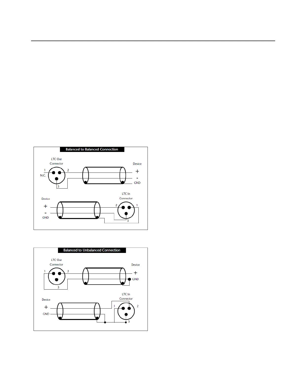
The Sync X LTC In and LTC Out connectors are balanced XLRs with Pin 2 wired “+” or “hot,” Pin 3 wired “–” or “cold,” and Pin 1
wired to ground (shield). Depending on whether you are connecting a balanced or unbalanced signal to these connectors, different wir-
ing configurations are recommended for optimum signal integrity, especially for long cable runs.
If you are connecting a balanced signal to the Sync X LTC In or LTC Out connectors:
Pin 1 and ground should be connected at the input only (not at the output). This will prevent ground loops between the shield and the
Pin 1 conductor.
If you are connecting an unbalanced signal to the Sync X LTC In or LTC Out connectors:
Connect only Pin 2 to the “+” signal;
Connect Pin 1 to ground at all inputs and outputs.
Refer to the following illustration for the correct wiring diagrams.
Wiring diagrams for the Sync X LTC In and LTC Out connectors