46
GPI Relay Wiring for Fader-Start
Sync X provides a total of four Relay-level GPI outputs on pins 3/4, 3–10 of the DB-25 connector (see the GPI Input, Output (Relay),
and Output (TTL) diagram).
The GPI Relay outputs are intended to drive Relay loads only.
GPI Triggers
GPI output signals information:
0 (relay) = Play
1 (relay) = Record Ready
2 (relay) = fader start #1
3 (relay) = fader start #2
4 (TTL) = Stop
5 (TTL) = Record
Logical GPI numbers 0 through 3 are associated with GPI relay outputs 0 through 3 (pins 3 through 10). GPI numbers 4 and 5 are as-
sociated with GPI TTL outputs 0 and 1 (pins 1 and 2).
GPI TTL Wiring
The circuit can drive approximately 2 mA through a load of 1.6K and maintain a logic high level of 3.3V. In an application where the
equipment being controlled has more demanding power requirements, an external buffer or relay circuit must be used. This would typ-
ically be constructed as part of a custom electrical interface.
Each GPI TTL output is fully short-circuit protected via a 150-ohm series resistor.
Before attempting to wire any type of custom interface, always check the electrical specifications provided by the equipment manufac-
turer, including voltage levels, current, loading and polarity. Incorrect wiring may damage your equipment, Sync X, or cause personal
injury.
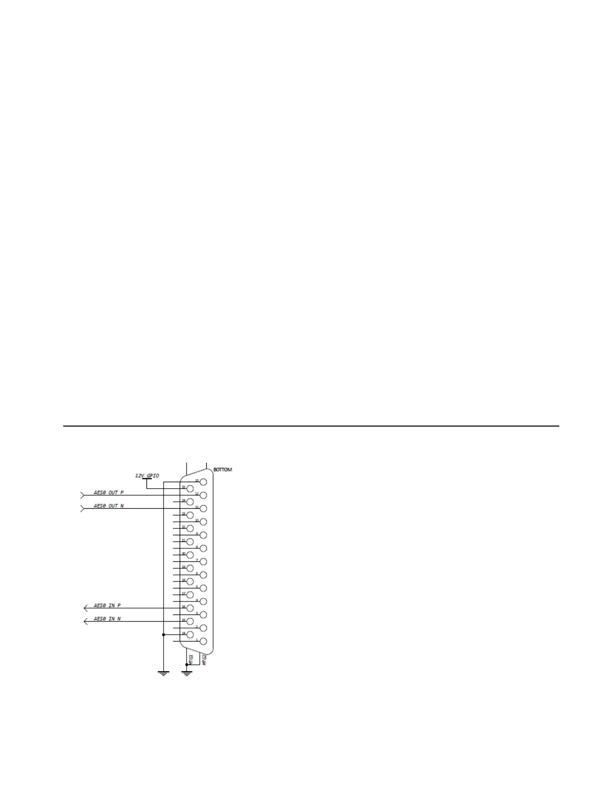
AES3 I/O DB-25 Port
AES3 I/O DB-25 pin-out