45
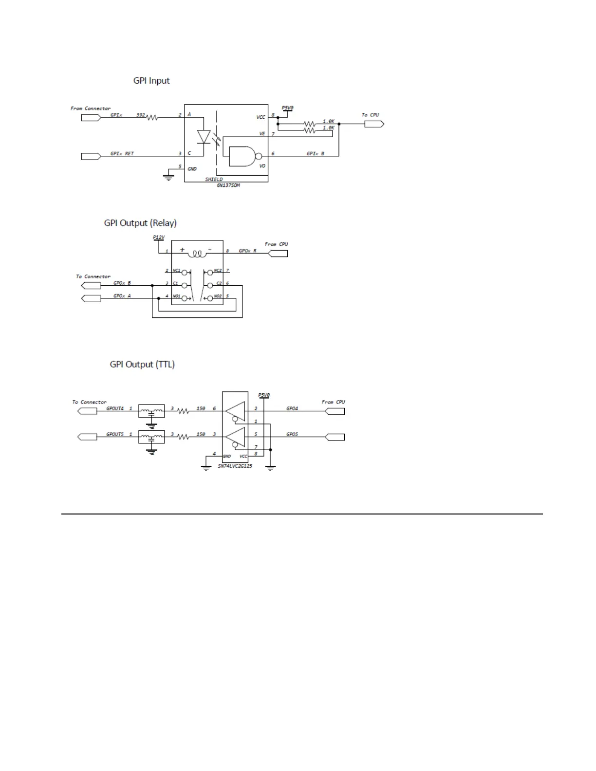
GPI Input, Output (Relay), and Output (TTL)
Bi-Phase/Tach/GPI/Pilot Port Interfacing Notes
The six opto-isolators are 6N137 devices. The four GPI input ports pass through 390 ohm series resistors to the cathode. The two
Bi-Phase/Tach inputs pass through 390 ohm series resistors to the cathode.
The two TTL-level GPI outputs are driven by a 74LVC2G125. Each output passes through a 150 ohm series resistor.
12 volts is supplied at the connector for the purpose of driving the opto-isolators in film tach applications. It is regulated and can sup-
ply up to 100mA.
For Tach, the “rate” input is “BIPHA_I” and the “direction” input is “BIPHB_I.” The polarity of “BIPHB_I” is software program-
mable and defaults to “low” for “forward.”
For Bi-phase, the default polarity relationship between A and B is software programmable. The default setting for “forward” is “A
leads B.” This means that the rising edge of A (0° phase) must precede the rising edge of B (90° phase).
For highest signal quality, use a 25-pin cable with individually shielded conductors.
GPI Input, Output (Relay), and Output (TTL)