EN - English - Instruction manual
22 MNGCEVO_2116_EN
6.10 Connecting the power
supply
6.10.1 24Vac/24Vdc power supply
Electrical connections must be performed
with the power supply disconnected and
the circuit-breaker open.
When commencing installation make sure
that the specifications for the power supply
for the installation correspond with those
required by the device.
Do not power the product using auto-
transformers.
Check that the power supply socket and
cable are adequately dimensioned.
For conductor section and cable sheath
diameters which can be used, please refer
to the technical data in the relevant chapter
(15 Technical data, page 30).
In case of continuous current power supply,
either polarity can be used.
To power the unit, use the power supply units
indicated in the technical data sheet of the product
on the website: avigilon.com, or use a toroidal
transformer with nominal power of at least 200VA.
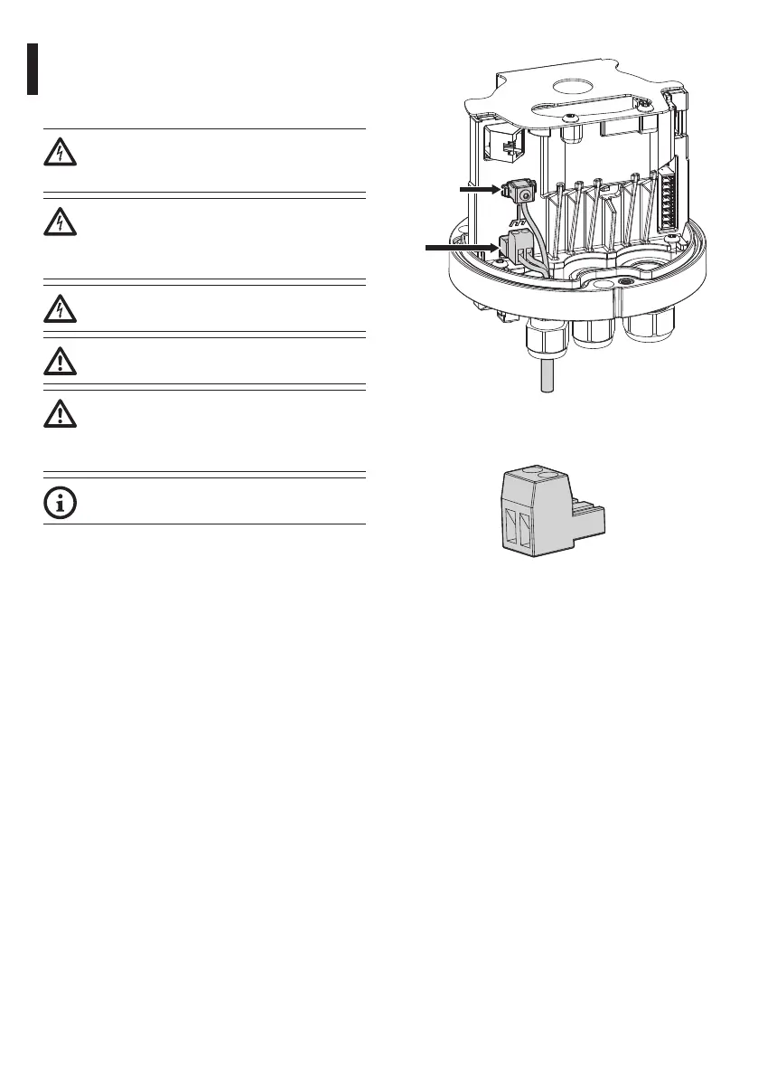
Connect the power supply cable to the relative
connector (J4, Fig. 23, page 22).
Connect the ground cable to the relevant terminal
(GND_INT, Fig. 23, page 22).
The power cables must be sized according to the
ratio between the supply current and the distance to
be covered.
If the product is powered by two sources of power
simultaneously (24V and PoE 90W), only the 24V line
will be used, disabling the PoE 90W power supply.
J4
GND_INT
Fig. 23
The removable connector is supplied in the kit.
Fig. 24
6.10.2 PoE 90W power supply
The product can be powered by 90W PoE according
to standard IEEE 802.3bt (CLASS 8).
The PoE injector must have at least 90W power.
By default, the product is configured to work
according to standard IEEE 802.3bt.
The use of the Phihong POE90U-1BT Injector is highly
recommended (POE-INJ-BT-90W-NA, Tab. 2, page 9).
If the product is powered by two sources of power
simultaneously (24V and PoE 90W), only the 24V line
will be used, disabling the PoE 90W power supply.
There are two DIP switches inside the base, which are
set by default as below:
• S1-DIP2 = OFF
• S2-DIP1 = OFF
For correct product operation, always leave S1-DIP2
and S2-DIP1 in the default position (S1 Fig. 21, page
21 and S2 Fig. 22, page 21).
 Loading...