Instruction manual - English - EN
23MNGCEVO_2116_EN
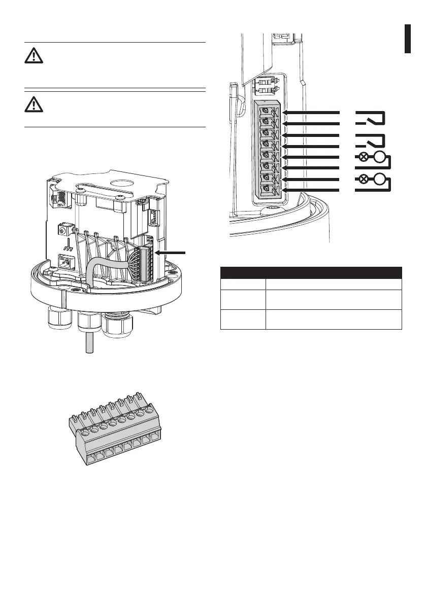
6.11 Alarm and relay connections
For conductor section and cable sheath
diameters which can be used, please refer
to the technical data in the relevant chapter
(15 Technical data, page 30).
Maximum relay voltage and current:
consult the technical data in the relevant
chapter (15 Technical data, page 30).
Connect the digital I/O cable to the relative connector
(J6, Fig. 25, page 23).
The maximum cable length for each alarm is 200m.
J6
Fig. 25
The removable connector is supplied in the kit.
Fig. 26
COM
COM
RL1A
RL1B
V
RL2A
RL2B
V
AL2
AL1
Fig. 27
CONNECTION OF THE ALARM INPUTS AND RELAYS
Terminals Description
RL1A, RL1B,
RL2A, RL2B
Clean contacts of the two relays which can be
activated via alarm or by user command
AL1, AL2, COM Self-powered alarm inputs referred to the shared
terminal
Tab. 4
The device can be equipped with a washing system
as an accessory. Connect the pump activation signal
cable to the indicated relay: RL2A, RL2B.
 Loading...