Service Manual
4.2.2 SENSOR INPUT
The sensor input includes home position sensor.
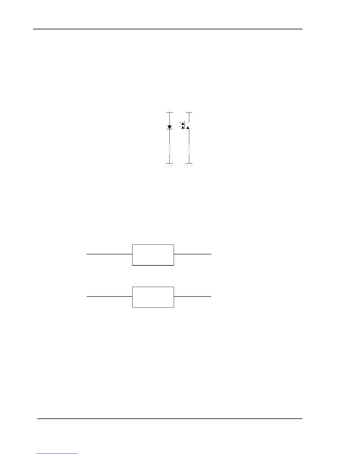
Home position sensor
The home position of the carrier motor is detected by photo sensor. The photo transistor
transmission to the photo sensor receiver circuit is shown below.
Figure 4.3 Home Sensor
The home position is detected when the carrier passes between the LED and the photo transistor.
4.2.3 SUB POWER SUPPLY CIRCUIT
The sub power supply circuit is provided for the internal analog circuit. Input is 24V and
output is Vcc and +5Va. The circuit configuration is shown below:
Figure 4.4 Power Aupply Circuit Configuration
The sub power supply is used for: A/D, and logic circuits.
+1.5V
+2.5V
+1.25V
+1.8V
+ 3.3 V
+ 32V
+ 16V