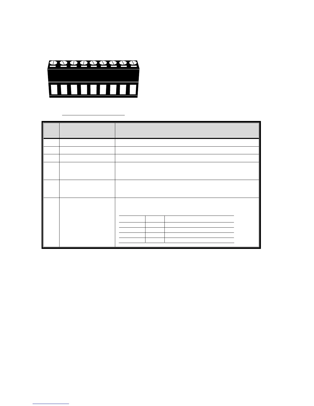
APPENDIX 6 PIN CONFIGURATION
76
A2. Models with HD video output
‧ With 9-pin external I/O block
123456
789
External I/O Block
PIN FUNCTION DESCRIPTION
1 GND GROUND
2 RS485-A
3 RS485-B
4
EXTERNAL ALARM
COM
Under the normal operation, COM disconnects with NO. But when any
alarm is triggered, COM connects with NO.
Attention: The voltage restriction is under DC24V 1A.
5
EXTERNAL ALARM
NO
Under the normal operation, COM disconnects with NO. But when any
alarm is triggered, COM connects with NO.
Attention: The voltage restriction is under DC24V 1A.
6~9 ALARM INPUT
Connect ALARM INPUT (PIN 6 -- 9) and GND (PIN 1) connector with
wires. Once an alarm is triggered, the DVR will start recording and the
buzzer will be on.
PIN Alarm Corresponding video channel
PIN 6 1 CH1
PIN 7 2 CH2
PIN 8 3 CH3
PIN 9 4 CH4
*