ENGINEERING DOCUMENTATION 11
_____________________________________________________________________________________________
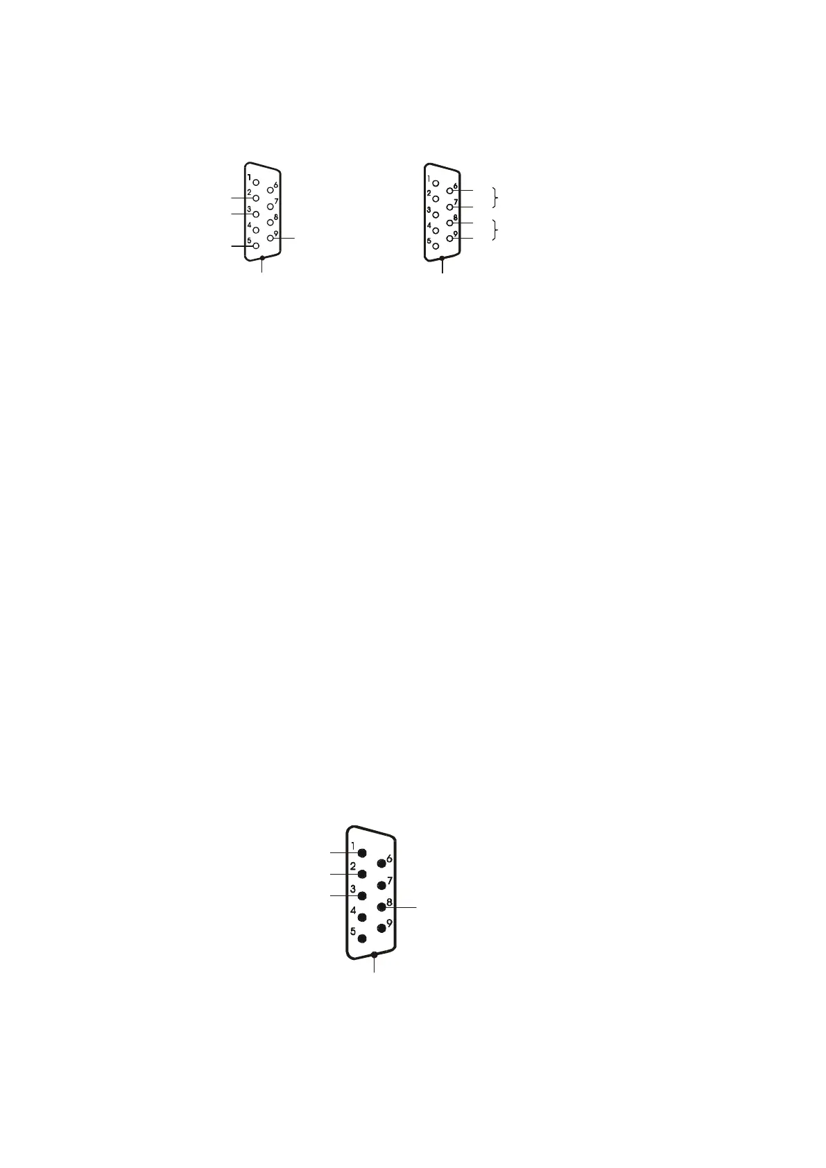
7.1 Comunication interfaces
RxD (receive)
TxD (transmit)
gnd
+5V(option)
casing
DE-9
RS485
DE-9
BB
IN
B
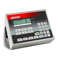
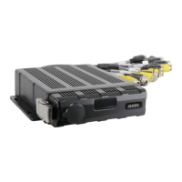
In SE-01/A/18 indicator an interface is placed on indicator’s housing. In SE-
01/N/... indicators interfaces are ends of wires which go out from an indicator.
Attention:
1.
To connect scale’s wire with RS232C interface (described above) to a
computer, RS232C adapter should be used which is included as the equipment of
SE-01/N/18 and SE-01/N/25 indicators (electric diagram of RS232C adapter is the
same as WK-1 wire).
2. In case of using the scanner, the RS232C port is divided into two separate
connectors. Receiver and 5V power supply are for the scanner, and transmitter for
the computer.
7.2 Transmitter interface
P1-P3 (THRESHOLDS) outputs are used to connect dosing or signaling (option)
devices. There are opto-isolators of an open collector type with 100mA / 24V
maximum load. They can be connected directly to transmitters inputs or to
MS3K/P board offered by AXIS separately or in ST 3K/P control box (3
transmitters, own power supply).
In SE-01/A/18 indicator THRESHOLD interface is placed on indicator’s housing.
P1 (próg I)
P2 (próg II)
P3 (zero)
GND
P1 (threshold I)
P2 (threshold II)
P3 (zero)