8 ENGINEERING DOCUMENTATION
_____________________________________________________________________________________________
7 Preparations
1. To build a scale basing on SE-01 indicator contact authorized manufacturer
service point or use Installation Guide delivered with the indicator.
2. The manufacturer gives a full guaranty for SE-01 indictor only when the
indicator was mounted by AXIS Sp. z o.o. In other cases the guaranty obligation
is taken over by the final contractor of the weighing device.
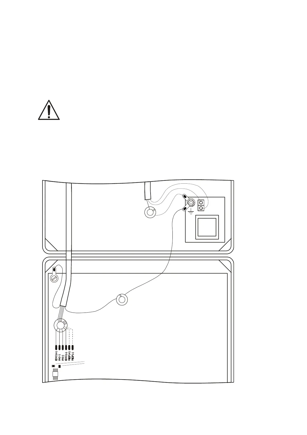
To comply CE marking requirements, for connecting the wires use filtering cores
delivered with the indicator, appropriate for signal type: sensor(s) wires – φ20mm
core, protecting wires - φ16mm (see the diagram below). The cores should be
placed within 30mm from the place of its connection.
Electric diagram SE-01/A:
When 6-wires connection of strain gauge transducers is used (REF+ and REF-)
jumpers shown on the picture above should be soldered out from the main board.
Before connecting the sensors to the indicator unplug the device from the
mains to avoid damaging the indicator!
Main board
cramps
mains protecting
wire 2 coil turns
signal wires - 4 coil turns
m
i
n
.
l
e
n
g
t
h