ENGINEERING DOCUMENTATION 9
_____________________________________________________________________________________________
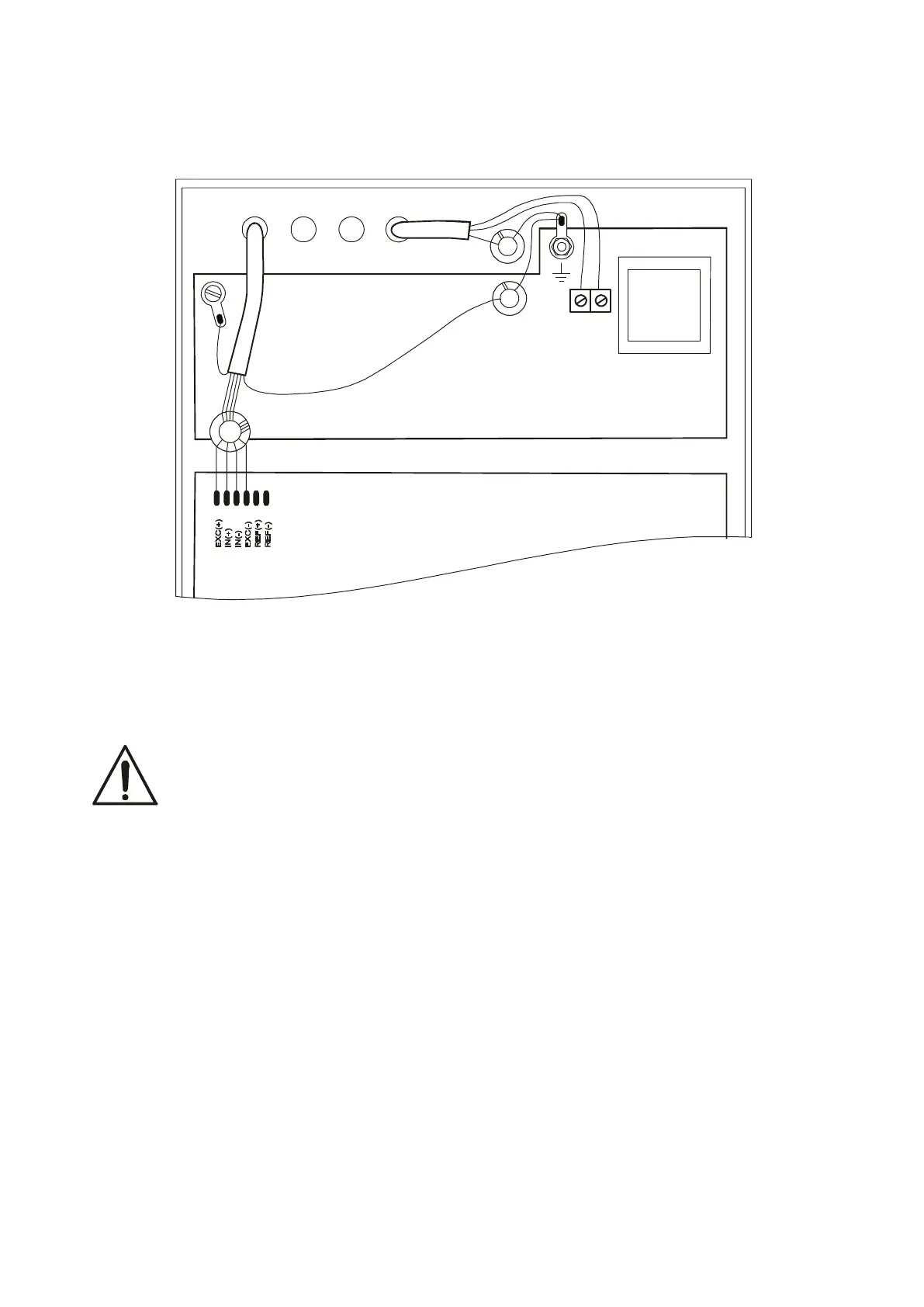
Electric diagram SE-01/N/18 and SE-01/N/25:
1. Connect the external devices cables to the meter sockets, or in the SE-01/N/..
meters to the board strip inside the meter, using the hermetic penetrations in the
housing (the SE-01/N.. strip drawing is shown below).
All devices should be powered from the same line (phase) 230V.
To feed the scale use only mains socket with ground contact.
sensor protecting
mains protecting
wire 2 coil turns
shield
signal wires - 4 coil turns