12 ENGINEERING DOCUMENTATION
_____________________________________________________________________________________________
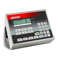
In SE-01/N/... indicators outer wires have digital markers.
Marker
No.
Signal Wire color*
1 P1 (I threshold) green
2 P2 (II threshold) white
3 P3 (zero) brown
10 GND (indicator ground) black or yellow
* colors can be changed
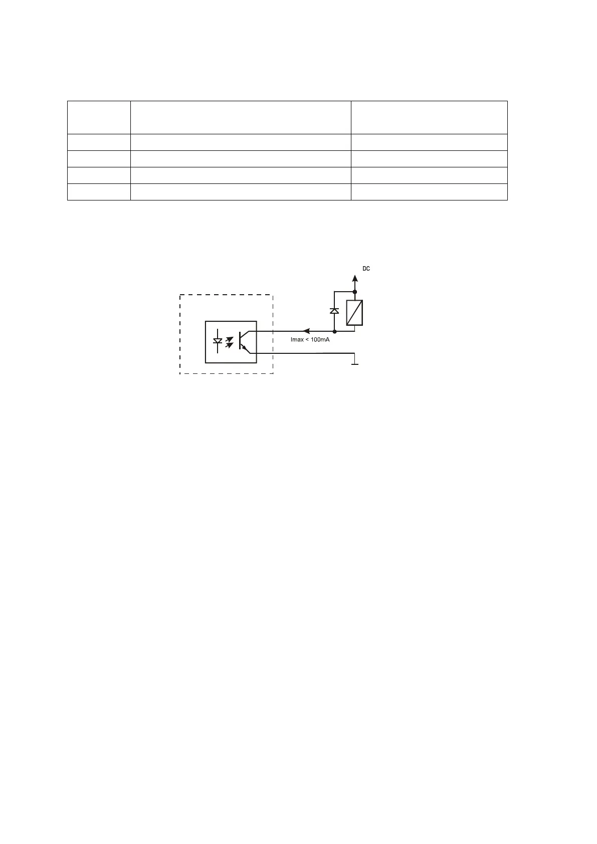
Diagram for direct connect a transmitter to THRESHOLD output:
0V
8
1
* in option without an interface – 10 is in the place of 8
Outputs are adapted for direct connect RM96P transmitter of DC24V input voltage
and AC250V 8A output. Transmitter’s coil has to be secured with diode e.g.
1N4148.
It is recommended to use MS 3K/P electronic board (3 transmitters of RM96P
type – max. load of 3A/250V) or complete ST 3K/P control (feeder, 3 transmitters
like above).
The way THRESHOLD outputs work is described in the separate document
(Special functions description).
7.3 External key interfaces
The input of external keys allows to place (make double) selected scale keys into
control box or operator’s workstation. As a standard the input is taken out with a
wire for direct connect to a control panel. SE-01/A/18 indicators can be equipped
with external key interfaces (as an option on demand).
External keys require external 24V DC feeder, which ensure galvanic isolation of
a scale from automatic systems.