Programming Page 23/51
MID_M2000_BA_02_1807
5.2.3 Inputs and outputs
Digital Outputs
In the sub-menu “Functional operation“, you can configure functional
operation of the 4 digital outputs. You can select e.g “forward pulse” for
the digital output and define the pulses per totalizer
scale”.
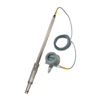
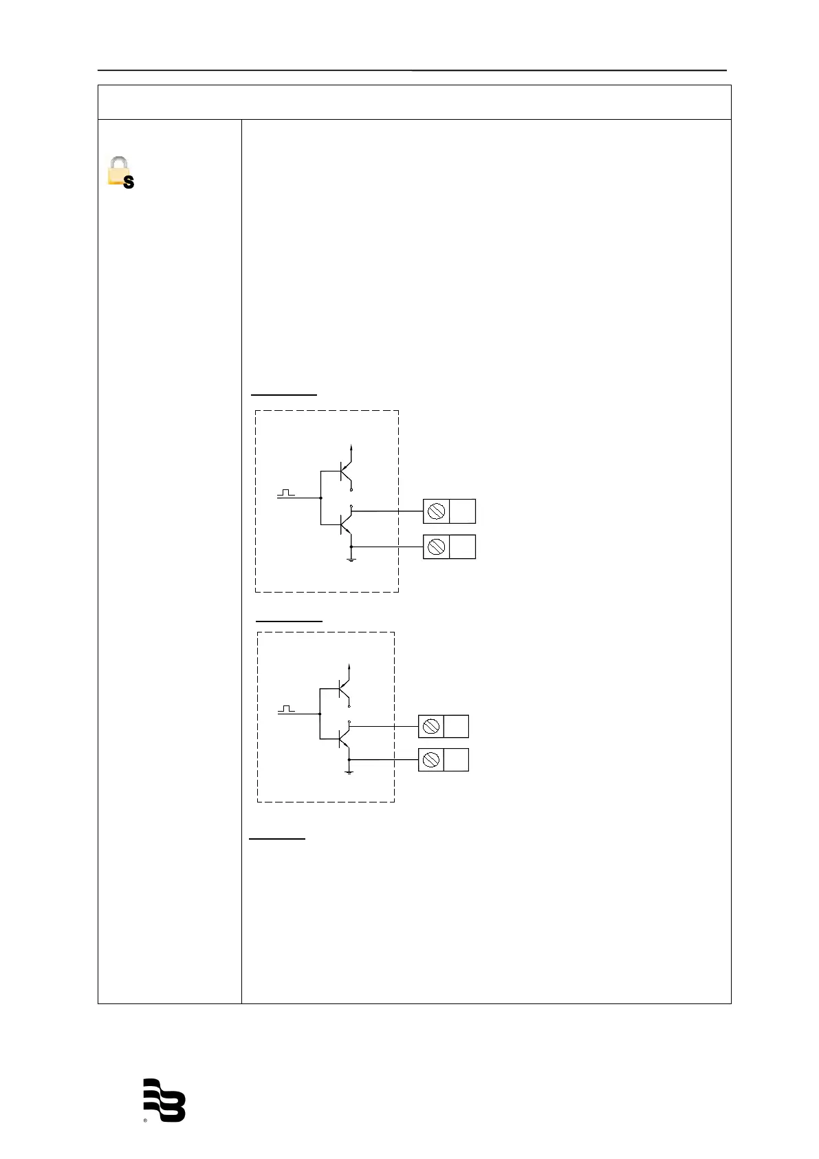
Digital outputs 1 and 2
The two outputs can be operated as open collector passively or actively.
Setting can be done via the hardware Jumper JP1 or JP2. Jumper
placed means “active output operation“,
otherwise “passive output
operation“. Jumper placement on circuit board, see chapter 4.3
Configuring inputs and outputs.
Caution:
If analog output and digital output 1 and 2 (only as open collector) are
used at the same time, we recommend the use of a galvanic isolation
(for example Phoenix Mini-Solid-State-Relais-OPT-24 VDC/24 VDC) of
the digital outputs to the external device (like SPS). This is necessary
as terminal COM (2) of digital output #1 and COM (4) of digital output
#2 are electrically connected to terminal 15(-) of the analog output. In
this case, the meter output must be active (JP1/JP2 set) to drive the
coupling relais.
Open collector 10 KHz
Passiv
e max. 30 VDC, 100 mA
e 24 VDC, 50 mA
Open collector 10 KHz
Passiv
e max. 30 VDC, 100 mA
ctive 24 VDC, 50 mA