OmniCare EVC System
Installation & Commissioning Manual
OmniCare issue 1
27
C
O
M
M
U
N
I
C
A
T
I
O
N
S
3.2.2.3 Connecting the Remote Unit
1. Connect the 10 way Blue Connector from the Termination
Board (item A in
Figure 3.5).
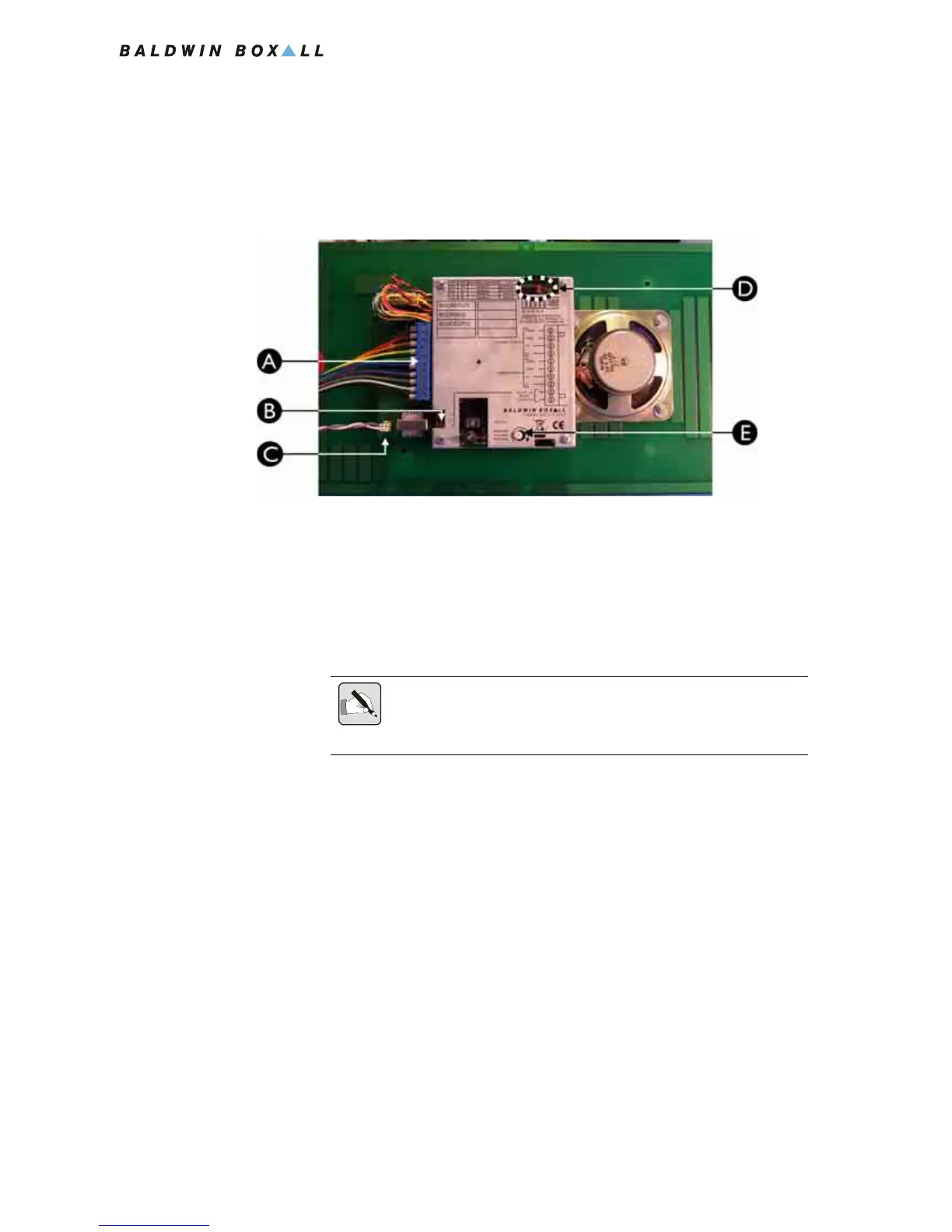
Figure 3.5 — Rear View of BVOCA Remote Unit
2. Fit the Remote Unit to the back box using the four T20 Torx
tamperproof screws supplied.
A Cable Termination Block
B J1 for controlling external equipment (NO or NC)
C Audio Output for Induction Loop Amplifier
D Option Jumpers - refer to Table 3.3 for details
E Speaker volume control
NOTE: Ensure the four links on the Termination Board (shown in Figure
3.4) are removed as the Remote Unit is now connected to the Circuit
Cabling.