OmniCare EVC System
Installation & Commissioning Manual
OmniCare issue 1
29
C
O
M
M
U
N
I
C
A
T
I
O
N
S
2. If required, remove the two screws securing the Remote
Unit sub-assembly to the back box to gain access to the top
two mounting holes and the Termination Board.
3. If not already fitted, mount the supplied back box at each
Remote Unit location.
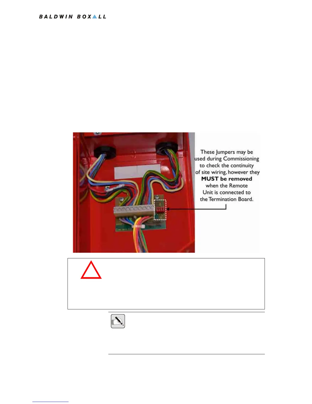
4. Terminate all cables at the termination board (shown in
Figure 3.7) according to the system designer's specifications
and the legend on the PCB. It is important that each
conductor is correctly identified before being terminated.
Figure 3.7 — BVFHL Enclosure with Termination Board
CA U T I O N
The OmniCare EVC System Remote Units can be damaged if
either of the following situations occur:
• If Power is connected across the Data pair,
• If Power is reversed i.e. 0V and +V swapped.
NOTE: It is important to ensure each connection to the termination board
is made correctly and the screw terminals are tightened sufficiently.
The majority of problems encountered during commissioning are due to
loose, poor, or incorrect terminations on Remote Units that impair the
integrity of the ring.