OmniCare EVC System
Installation & Commissioning Manual
OmniCare issue 1
31
C
O
M
M
U
N
I
C
A
T
I
O
N
S
2. Ensure the Telephone Handset Connector (item C in Figure
3.8) is connected to the pin header on the circuit board.
3. Carefully rotate the electronics sub-assembly so that the front
face panel is facing outwards, and then locate the bottom
tongue in the slot in the rear of the back box.
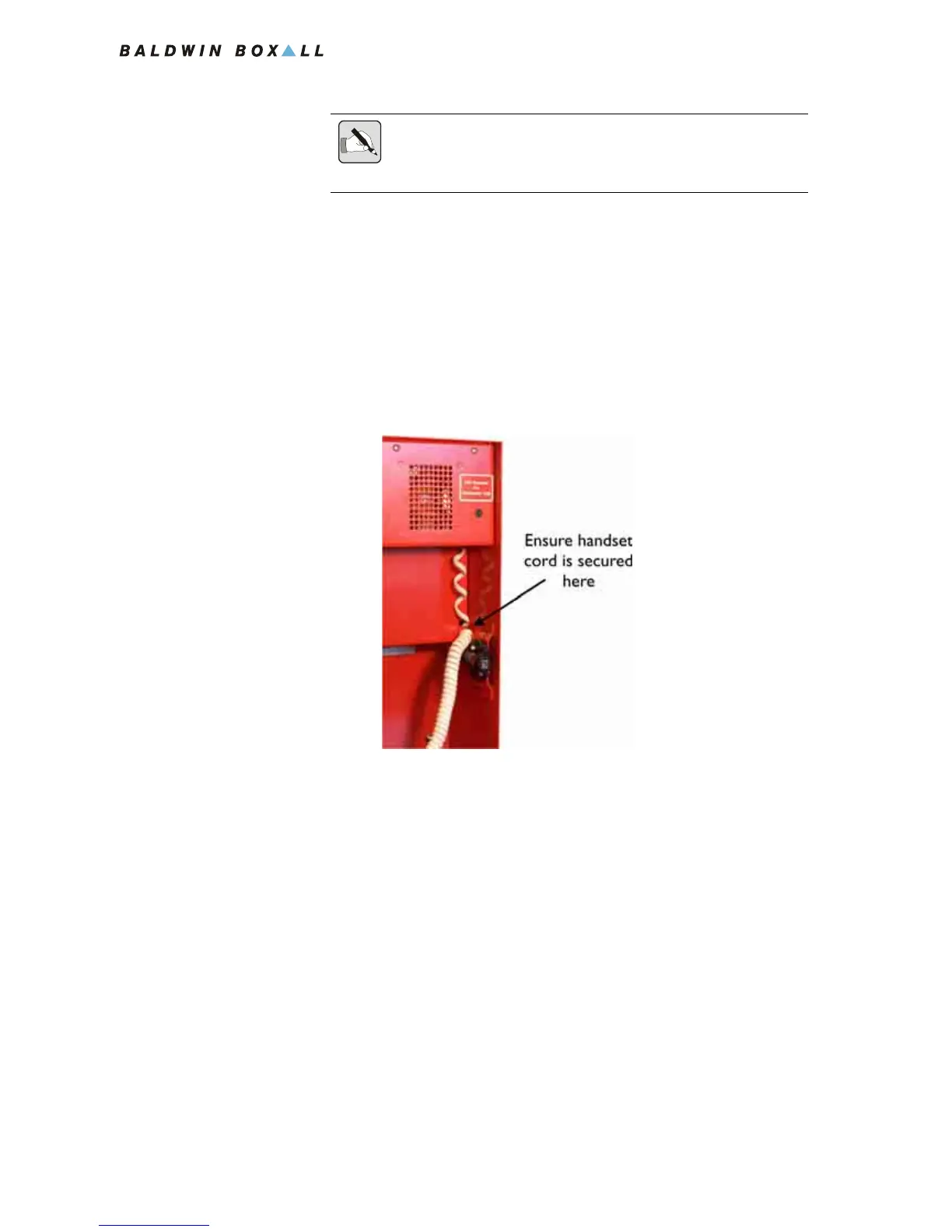
4. Ensure the Handset Cable is secured in place correctly as
shown in
Figure 3.9.
Figure 3.9 — Correct Handset Cable position
5. Fit the two screws at the top of the front panel to hold the
Remote Unit in the back box.
NOTE: Ensure the four links on the Termination Board (shown in Figure
3.7) are removed as the Remote Unit is now connected to the Circuit
Cabling.