OmniCare EVC System
Installation & Commissioning Manual
OmniCare issue 1
35
C
O
M
M
U
N
I
C
A
T
I
O
N
S
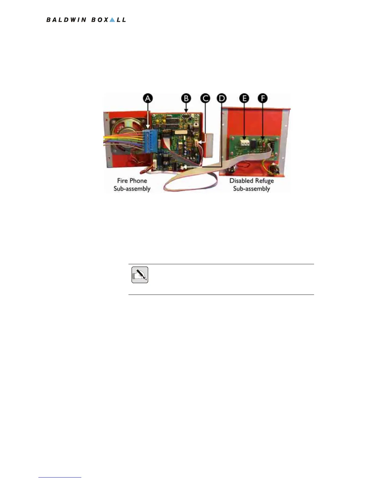
3.2.4.3 Connecting the Remote Unit
1. Connect the 8 way Blue Connector from the Termination
Board (item A in
Figure 3.12).
Figure 3.12 — Rear View of BVOCRFC Remote Unit
2. Ensure the Telephone Handset Connector (item C in Figure
3.8) is connected to the pin header on the circuit board.
3. Refit the Disabled Refuge front panel to the back box.
4. Carefully rotate the Fire Phone sub-assembly so that the front
face panel is facing outwards, and then locate the bottom of
the tongue in the slot in the rear of the back box.
5. Ensure the Handset Cable is secured in place correctly as
shown in
Figure 3.9 on page 31.
6. Fit the two screws at the top of the front panel to hold the
Fire Phone sub-assembly in place.
7. Ensure the ribbon cable is secured using the clip provided.
A Cable Termination Block
B Option Jumpers J2 - J6 see section 3.2.4.2 for details
C Handset connector
D Volume control
E External Relay connections
F Reset Option Jumper J1 see section 3.2.4.2 for details
NOTE: Ensure the four links on the Termination Board (shown in Figure
3.7) are removed as the Remote Unit is now connected to the Circuit
Cabling.