OmniCare EVC System
Installation & Commissioning Manual
38 OmniCare issue 1
C
O
M
M
U
N
I
C
A
T
I
O
N
S
3.2.5.3 Notes on Configuring BVOCDTA & BVFREPEM
The normal configuration for the BVFREPEM when used as an
interface for an
OmniCare EVC System is SW3 and SW4 "ON" as
shown in
Table 3.9.
This configuration will automatically place all Toilet Alarms
together on the Control Panel at the end of the detected Remote
Units. They will be in the order they are wired around the loop.
If this grouping is not required it is possible to set the units to
appear on the Control Panel in the position that they are cabled
around the loop. To use this alternative set SW3 to "ON" and
SW4 to "OFF" (as for FireCare).
It is possible to re-address BVFREPEM Remote Units to appear
at alternative locations. For further information on re-addressing
please refer to
Section 5.4 on page 67.
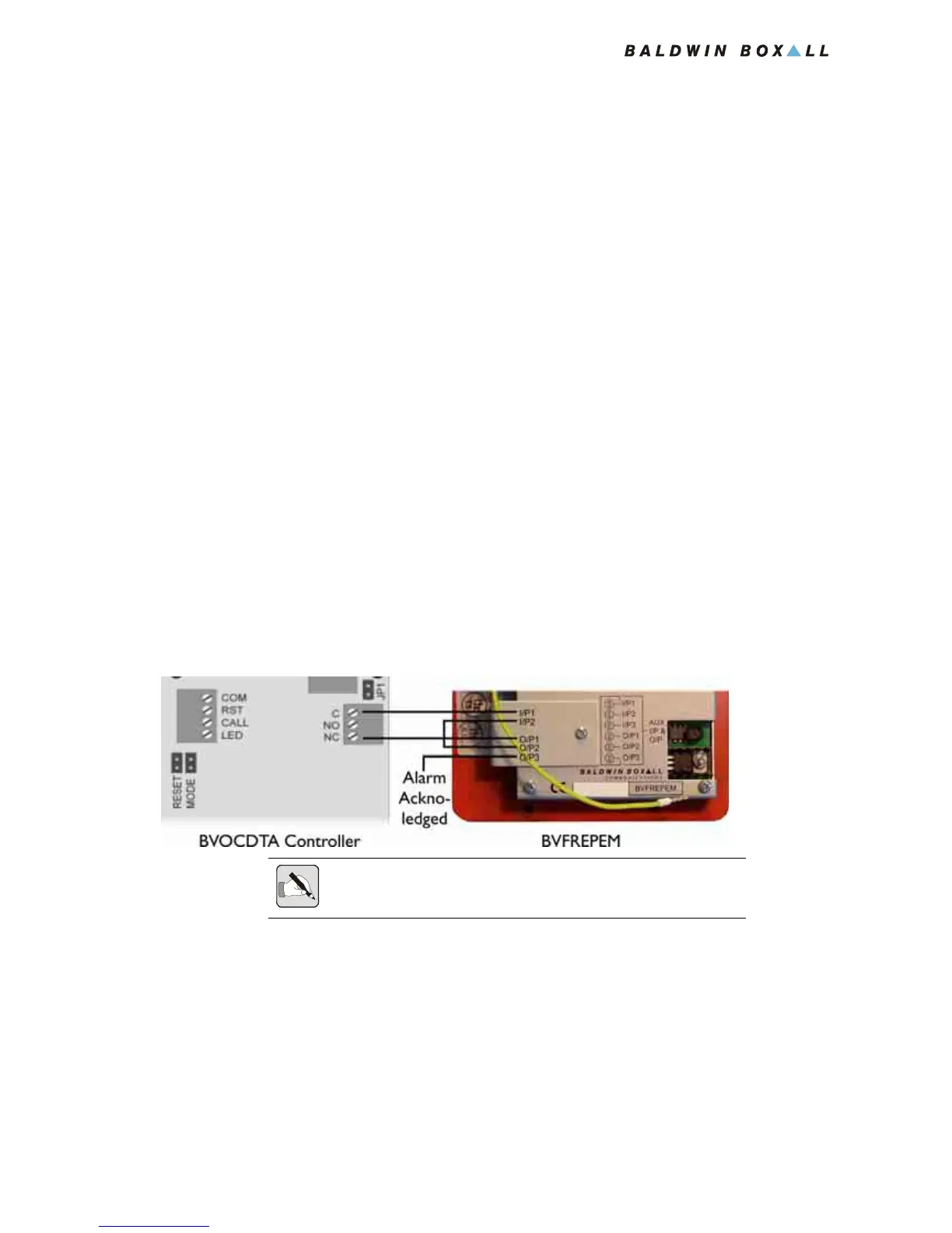
3.2.5.4 Connecting the BVOCDTA to the BVFREPEM
1. Connect the BVOCDTA Controller to the BVFREPEM as
shown in
Figure 3.14.
Figure 3.14 — Connections between BVOCDTA and BVFREPEM
2. If required an "Alarm Acknowledged" indicator can be
connected to O/P3 (Open Collector output, 50mA max).
3. Refit the retaining brackets over the blue termination blocks
and replace the screws.
4. Connect the green and yellow safety earth lead to the earth
terminal in the back box.
5. Fit the Remote Unit to the back box using four screws.
NOTE: The BVFREPEM includes a NC Fault Input between I/P2 and
O/P2. These must be linked to prevent a fault being announced.