www.balluff.com 15english
6
Calibration procedure
6.1 Calibration device (not for BTL7-…-S140)
The calibration device is an additional device for calibrating
the transducer.
► Before calibrating: Place the calibration device on the
connection side of the transducer.
► When finished with calibration: Remove the calibration
device to prevent changes.
► Keep the calibration device for later use.
Automatic deactivation!
If the buttons on the calibration device are not
pressed for approx.10min., programming
mode is automatically ended.
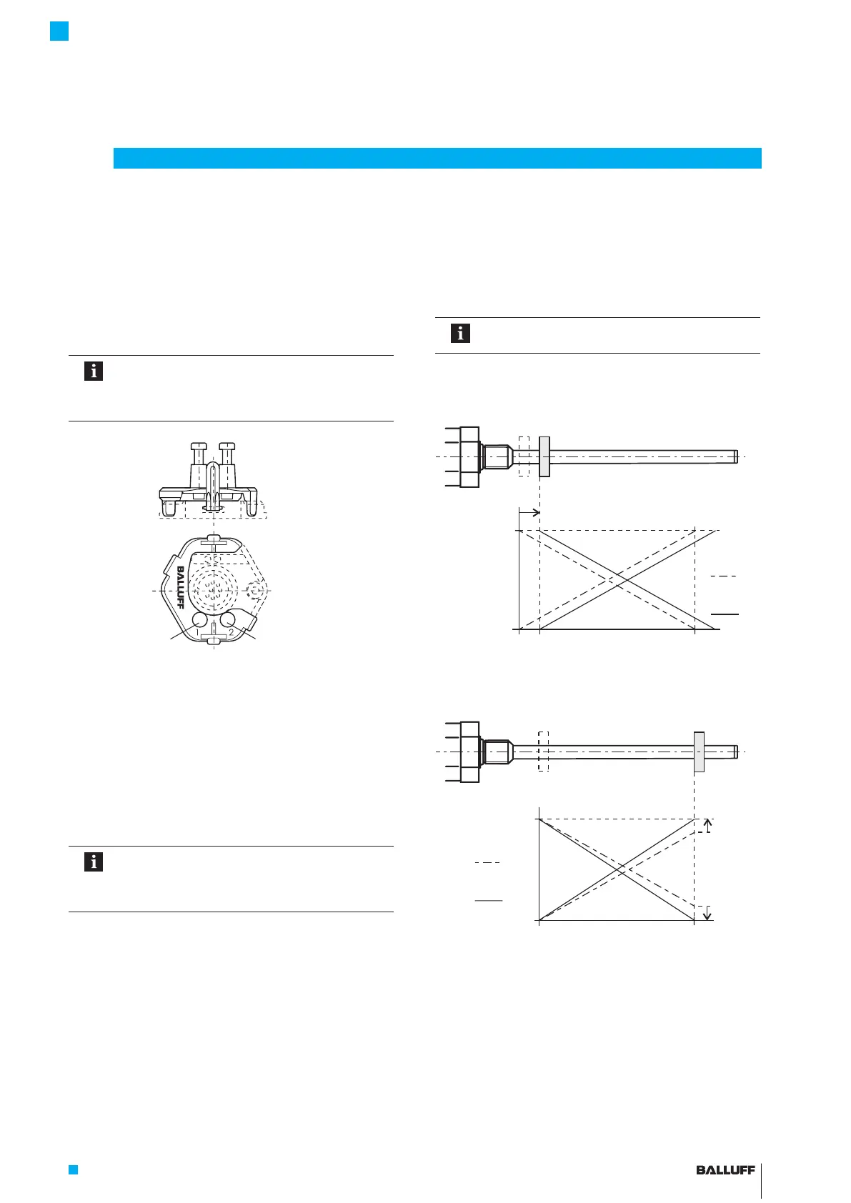
Fig. 6-1: Calibration device in place
6.2 Programming inputs (not for BTL7-…-S135)
Instead of the calibration device, the programming inputs
may also be used for setting.
– La corresponds to button 1,
– Lb corresponds to button 2,
– Programming input at 20 to 28V (BTL7-_1_ _-...) or 10
to 30V (BTL7-_5_ _-...) corresponds to button
depressed (high active).
Automatic deactivation!
If no signals are sent over the programming
inputs for approx.10min., programming mode
is automatically ended.
6.3 Calibration procedure overview
6.3.1 Teach-in
The factory set null point and end point is replaced by a
new null point and end point.
The detailed procedure for teach-in is described
on page 18.
Steps:
► Move magnet to the new zero position.
► Read new null point by pressing the buttons.
Fig. 6-2: Reading new null point (offset shift)
► Move magnet to the new end position.
► Read new end point by pressing the buttons.
Fig. 6-3: Reading new end point (changing the output gradient)
New null point
Before
After
Falling
Rising
New end point
Before
After
New measuring length 100%
Button 1 (blue) Button 2 (gray)
BTL7-A/C/E/G_ _ _-M_ _ _ _-A/B/Y/Z(8)-S32/S115/S135/S140/KA_ _/FA_ _
Micropulse Transducer - Rod Style

 Loading...


