+24V dc
+
0V dc
S1
S2
Y4
Y2
14
24
34
S3
S4
Y3
Y1
13
23
33
K2 K1
Machine
Control
Feedback (optional)
MPCE
2
MPCE
1
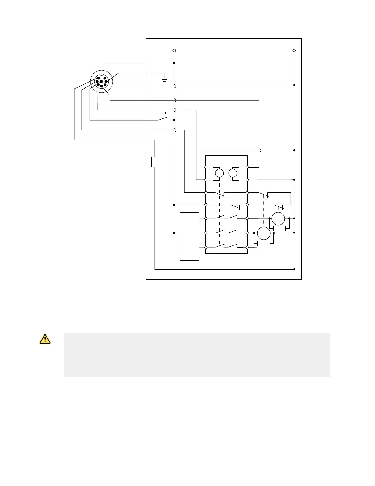
Receiver
8-pin male
Euro-style
face view
IM-T-9A***
Aux. out
Bn (Pin #1)
Gn/Ye (#7)
Bu (#6)
Bk (#5)
Wh (#4)
Vi (#8)
Or (#3)
Or/Bk (#2)
*
*
Reset**
Figure 23. Interface Module (1-channel EDM, with reset)—Generic Wiring
* Installation of transient (arc) suppressors across the coils of MPCE1 and MPCE2 is recommended.
** Trip (auto reset) — Not connected
*** Other interfacing modules and solutions available.
† See
Accessories
on page 88 for more QDE-8D cordset information.
WARNING:
• Properly install arc or transient suppressors
• Failure to follow these instructions could result in serious injury or death.
• Install any suppressors as shown across the coils of the machine primary control elements. Do
not install suppressors directly across the output contacts of the safety or interface module. In
such a
configuration, it is possible for suppressors to fail as a short circuit.
EZ-SCREEN
®
14/30 mm Safety Light Screen
www.bannerengineering.com - Tel: + 1 888 373 6767 47