23 © Banner Engineering Corp. www.bannerengineering.com
SENSOR PROGRAMMING
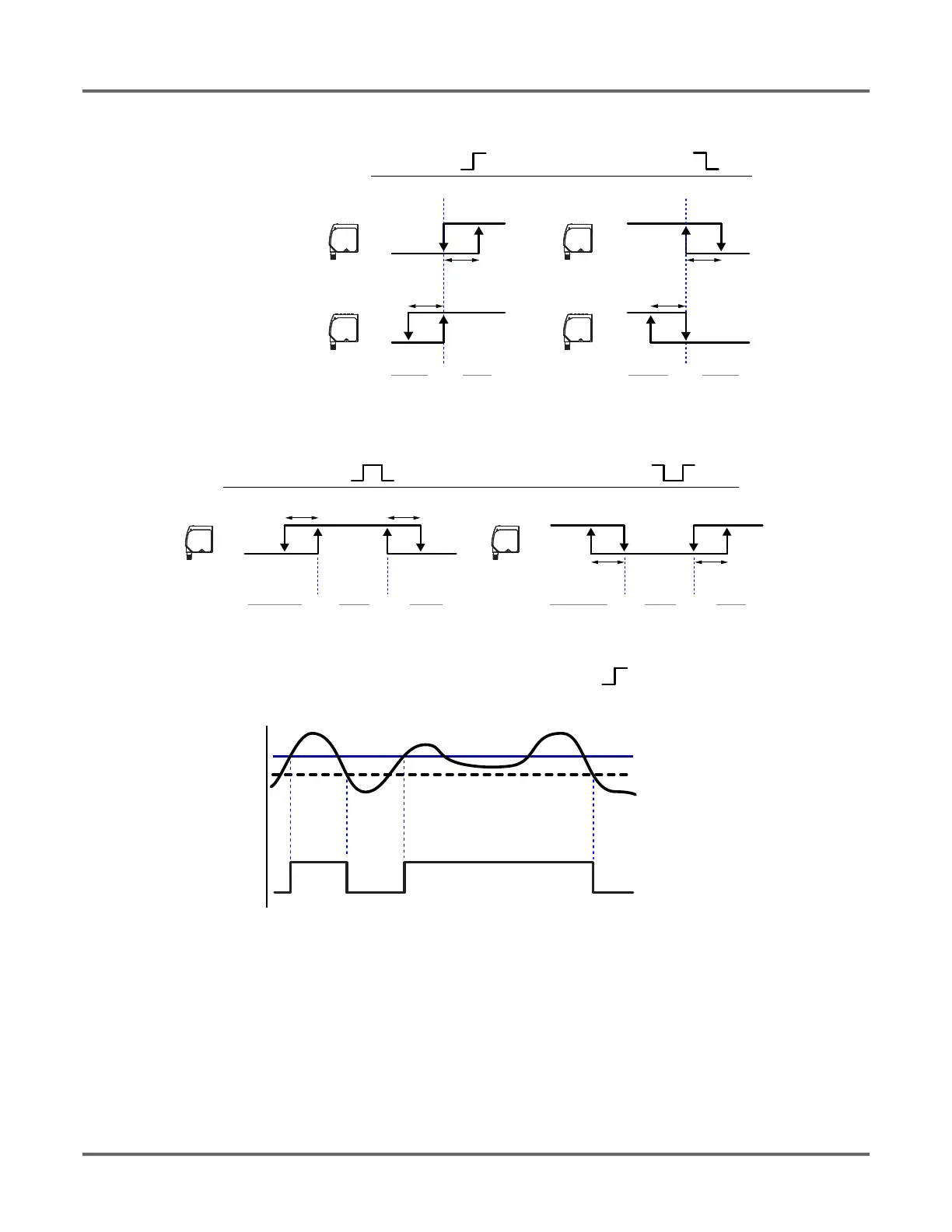
Figure 11: How hysteresis affects the sensor output based on the discrete output switchpoint mode and the setpoint reference mode
Figure 12: How hysteresis affects the two discrete output window modes
Figure 13: How hysteresis affects the output on/off points when if the sensor is configured with mode = Swtch_|- and SPtRef configured as Backgrnd
Press the up button to manually select a constant hysteresis value between 2 mm and 11950 mm for the LTF12 and between 2 mm and 23950
mm for the LTF24 models.
Navigate: MENU > D_OUT > Hyst
Remote Input: Not available
Default: Auto
Object
(Object)
Setpoint Reference
(SPtRef)
Mode
SPt SPt
Background
(Backgrnd)
Hyst
On
Output
(On/Off)
Off
Near Far Near Far
On
Off
Hyst
Hyst
Hyst
On
Off
On
Off
Swtch Swtch
Output
(On/Off)
Mode
SPt1
Hyst Hyst
On
Off
Near Far
Wnd Wnd
Output
(On/Off)
SPt2 SPt1
Hyst Hyst
On
Off
Near Far
Output
(On/Off)
SPt2
On
Off
Near
Far
Setpoint
Hysteresis
Signal
Output
Setpoint Mode Example:
Mode = Swtch
SPtRef = Backgrnd
 Loading...