© Banner Engineering Corp. www.bannerengineering.com 32
SENSOR PROGRAMMING
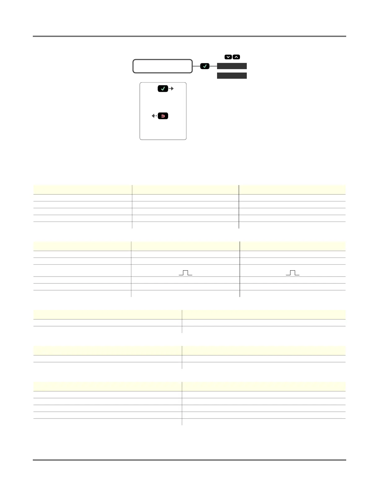
Figure 28: Reset Menu Map
3.12. Factory Default Settings
Analog Output Settings LTF12 LTF24
Adjust 4 mA (0 V) 50 mm 50 mm
Adjust 20 mA (10 V) 12000 mm 24000 mm
Loss of Signal 3.5 mA (0 V) 3.5 mA (0 V)
Slope Positive Positive
Window Size 2000 mm 2000 mm
Discrete Output Settings LTF12 LTF24
Adjust Switch Point One 50 mm 50 mm
Adjust Switch Point Two 12000 mm 24000 mm
Mode
Wnd Wnd
Polarity PNP PNP
Timer 0 ms for all timers 0 ms for all timers
Window Size 20 mm 20 mm
Input Settings Value
Input Active Low
Input Type Disabled
Measure Settings Value
Speed Medium
Trigger Sample
Display Settings Value
Sleep Disabled
Units mm
Zero Near
Shift Off
View Normal
MENU RESET
or
or
Go Back to Parent Menu
Select Menu Item
Press to Save Setting
Press and Hold to Go Back
to Run Mode
RESET No
RESET Yes
 Loading...