© Banner Engineering Corp. www.bannerengineering.com 4
SENSOR INSTALLATION
2. Sensor Installation
NOTE: Handle the sensor with care during installation and operation. Sensor windows soiled by fingerprints, dust, water, oil, etc. may create stray
light that may degrade the peak performance of the sensor. Blow the window clear using filtered, compressed air, then clean as necessary using
70% isopropyl alcohol and cotton swabs or water and a soft cloth.
2.1. Mount the Device
1. If a bracket is needed, mount the device onto the bracket.
2. Mount the device (or the device and the bracket) to the machine or equipment at the desired location. Do not tighten the mounting
screws at this time.
3. Check the device alignment.
4. Tighten the mounting screws to secure the device (or the device and the bracket) in the aligned position.
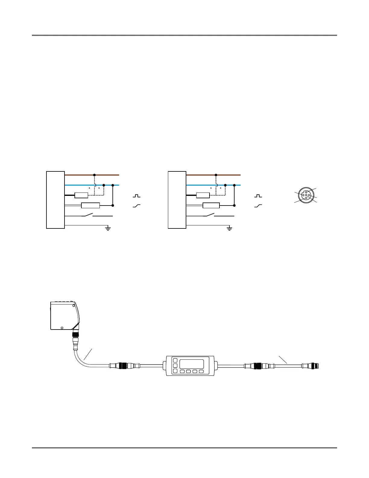
2.2. Wiring Diagrams
2.3. Connecting to RSD1
The following diagram depicts the connection of the LTF to the optional RSD1 accessory.
Figure 3: LTF to RSD1
Use these cordsets to connect the RSD1 to the LTF sensor or to other devices, such as PLC inputs, IO-Link masters, or control systems.
Figure 1: Analog Current Model Figure 2: Analog Voltage Model
Key
• 1 = Brown
• 2 = White
• 3 = Blue
• 4 = Black
• 5 = Gray
shield
+
12-30V dc
D_Out
A_Out
Input
–
Load
* User-configurable PNP/NPN setting
4-20 mA
3
1
2
4
5
NPN
or
PNP
shield
+
12-30V dc
D_Out
A_Out
Input
–
Load
* User-configurable PNP/NPN setting
3
1
2
4
5
NPN
or
PNP
0-10V
MQDEC3-503SS
Double Ended Shielded
MQDEC3-506SS
MQDEC3-515SS
MQDEC3-530SS
MQDEC2-506
Flying Lead Shielded
MQDEC2-515
MQDEC2-530
RSD1
LTF
MQDEC3-503SS
Double Ended Shielded
MQDEC3-506SS
MQDEC3-515SS
MQDEC3-530SS
 Loading...