P/N 133487 111
Banner Engineering Corp. • Minneapolis, U.S.A.
www.bannerengineering.com • Tel: 763.544.3164
SC22-3 Safety Controller
Instruction Manual
Appendix B
Export Documents (see Section 4.5.7)
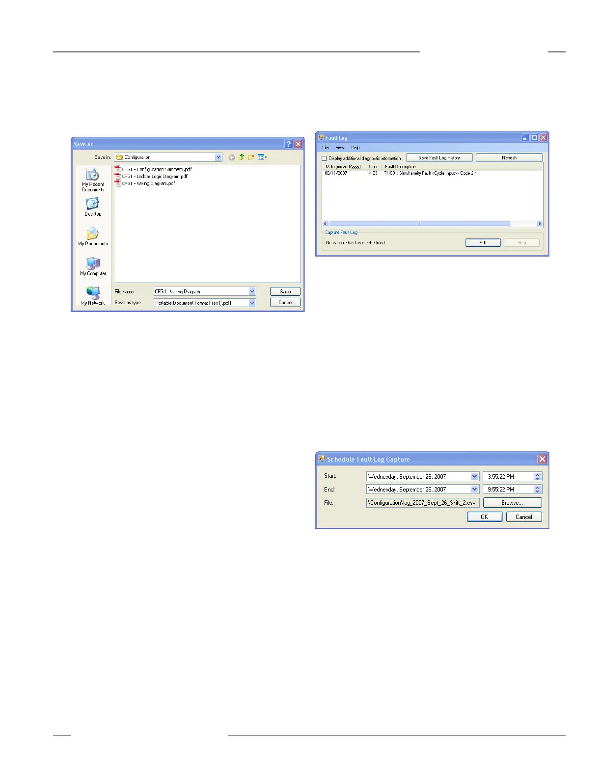
The configuration wiring diagram, ladder logic diagram and
configuration summary documents can be saved as either .pdf or
.dxf files.
To export a configuration file:
• Open the configuration file that you want to save.
• Open the File menu in the upper left of the PCI tool bar.
• Select Export.
• Select the configuration document to export.
• Verify that the file name is correct and select the appropriate
Save as type file option from the drop-down field (either .pdf
or.dxf file format).
• Click <Done>.
Print Options (see Section 4.5.8)
To print a configuration file:
• Open the configuration file that you want to print
• Open the File menu in the upper left of the PCI tool bar.
• Select Print.
• Select the configuration document you want to print. A page
setup menu will appear.
• Make the page and printer choices and click OK.
Fault Log
To access the Controller’s internal Fault Log using the PCI:
• Connect the SC22-3 Controller to the PC using the USB cable.
• Apply 24V dc power to the Controller.
• Open the View menu in the PCI tool bar.
• Select Fault Log.
The Fault Log screen will appear and will display any I/O or
system faults detected by the Safety Controller.
Scheduled Fault Log Capture
Controller I/O and system fault information can be recorded to a
computer file. To set up a recording period to capture fault data
from a Controller, access the Fault Log menu.
• Connect the SC22-3 Controller to the PC using the USB cable.
• Apply 24V dc power to the Controller.
• Open the View menu in the tool bar.
• Select Fault Log.
• Select the Edit button.
• Set the Start and End times, using the drop-down fields.
• Browse for the File location.
• Click OK.
The fault data will be stored to this file location as an Excel file.