force a sequenced reset routine, which can be used to reduce or eliminate pass-through hazards in perimeter guarding
applications (see Safety Input Device Properties on page 69).
If the controlling inputs to a Latch Reset Block or a Safety Output Block are not in the Run state, the reset for that block
will be ignored.
Reset Signal Requirements
Reset Input devices can be configured for monitored or non-monitored operation, as follows:
Monitored reset: Requires the reset signal to transition from low (0 V dc) to high (24 V dc) and then back to low. The
high state duration must be 0.5 to 2 seconds. This is called a trailing edge event.
Non-monitored reset: Requires only that the reset signal transitions from low (0 V dc) to high (24 V dc) and stays high
for at least 0.3 seconds. After the reset, the reset signal can be either high or low. This is called a leading-edge event.
Muting Block
Default Nodes
Additional Nodes Notes
IN
MP1
MP2
ME
BP
Muting Sensor Pair input blocks must be connected directly to the Muting function block.
One Way - 1 Mute Sensor Pair
Two Way - 1 Mute Sensor Pair
One Way - 2 Mute Sensor Pair
Two Way - 2 Mute Sensor Pair
Two Way - 1 Mute Sensor Pair
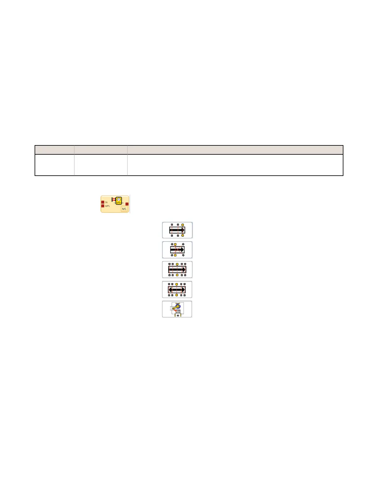
Mute Function Block
There are five Mute Function types listed below. The following timing diagrams show the
function detail and sensor/safeguarding state change order for each mute function type.
Figure 24. Muting Block—Function Types
XS/SC26-2 Safety Controller
32

 Loading...


