The level of the safety circuit integrity must be determined by risk assessment; this level is dependent on the
configuration, proper installation of external circuitry, and the type and installation of the devices under control (FSDs and
MPCEs). The solid-state safety outputs are suitable for Category 4 PL e / SIL 3 applications when controlled in pairs (not
split) and for applications up to Category 3 PL d / SIL 2 when acting independently (split) when appropriate fault exclusion
has been employed. See Figure 67 on page 88 for hookup examples.
WARNING: Safety Output Lead Resistance
To ensure proper operation, the resistance in the safety output wires should not exceed 10
ohms. A resistance higher than 10 ohms may mask a short between the dual-channel safety outputs
and create an unsafe condition that may lead to serious bodily injury or death.
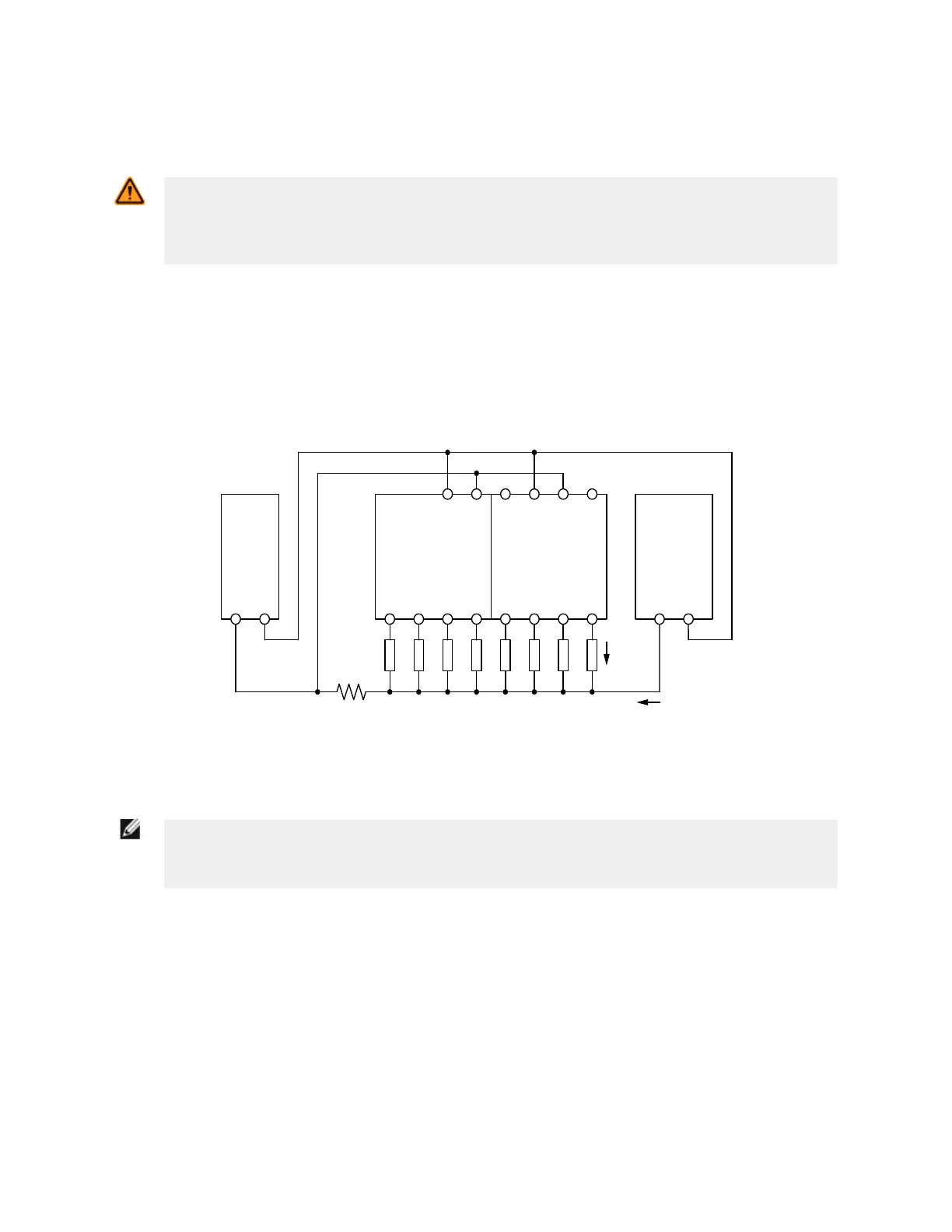
Common Wire Installation
Consider the wire resistance of the 0 V common wire and the currents flowing in that wire to avoid nuisance lockouts.
Notice the location of the resistance symbol in the diagram below representing 0 V common wire resistance (RL).
Methods to prevent this situation include:
• Using larger gauge or shorter wires to reduce the resistance (R
L
) of the 0 V common wire
• Separate the 0 V common wire from the loads connected to the safety controller and the 0 V common wire from
other equipment powered by the common 24 V supply
XS2so
Solid State Safety
Output Module
XS26-2 Expandable
Safety Controller
Power
Supply
0V 24V
24V 0V24V 0V
R
L
= Common leadwire shared by multiple loads or systems
Sharing of small gauge leadwire can lead to faults on
solid state outputs.
Load
current
Other current
R
L
Other
Equipment
0V 24V
Figure 67. Common Wire Installation
NOTE: When the Safety Output turns Off, the voltage at that output terminal must drop below 1.7 V
with respect to the 0V terminal on that module. If the voltage is higher than 1.7 V, the Controller will
decide that the output is still on resulting in a lockout. Consider using larger gauge wires, shorter wires,
or using a single point grounding scheme similar to what is shown in the following diagrams.
XS/SC26-2 Safety Controller
88