2. CS-100 Specifications
LEDs behavior Explanation
breathing white
• ECO standby mode
static w hite
• awake and ready (i.e. showing the welcome mess age on the display)
• pairing is done
red blinking
• an e rro r occurred
dark
• deep standby/off
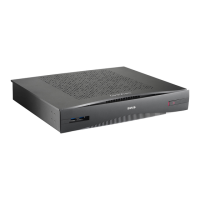
Power button
The button at the front of the Base Unit has a power on/off function once the Base unit is powered
• When the system is powered on, a push m akes the system shut d own and power off.
• When the system is shut down, a push triggers the system to s tart up.
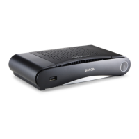
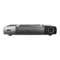
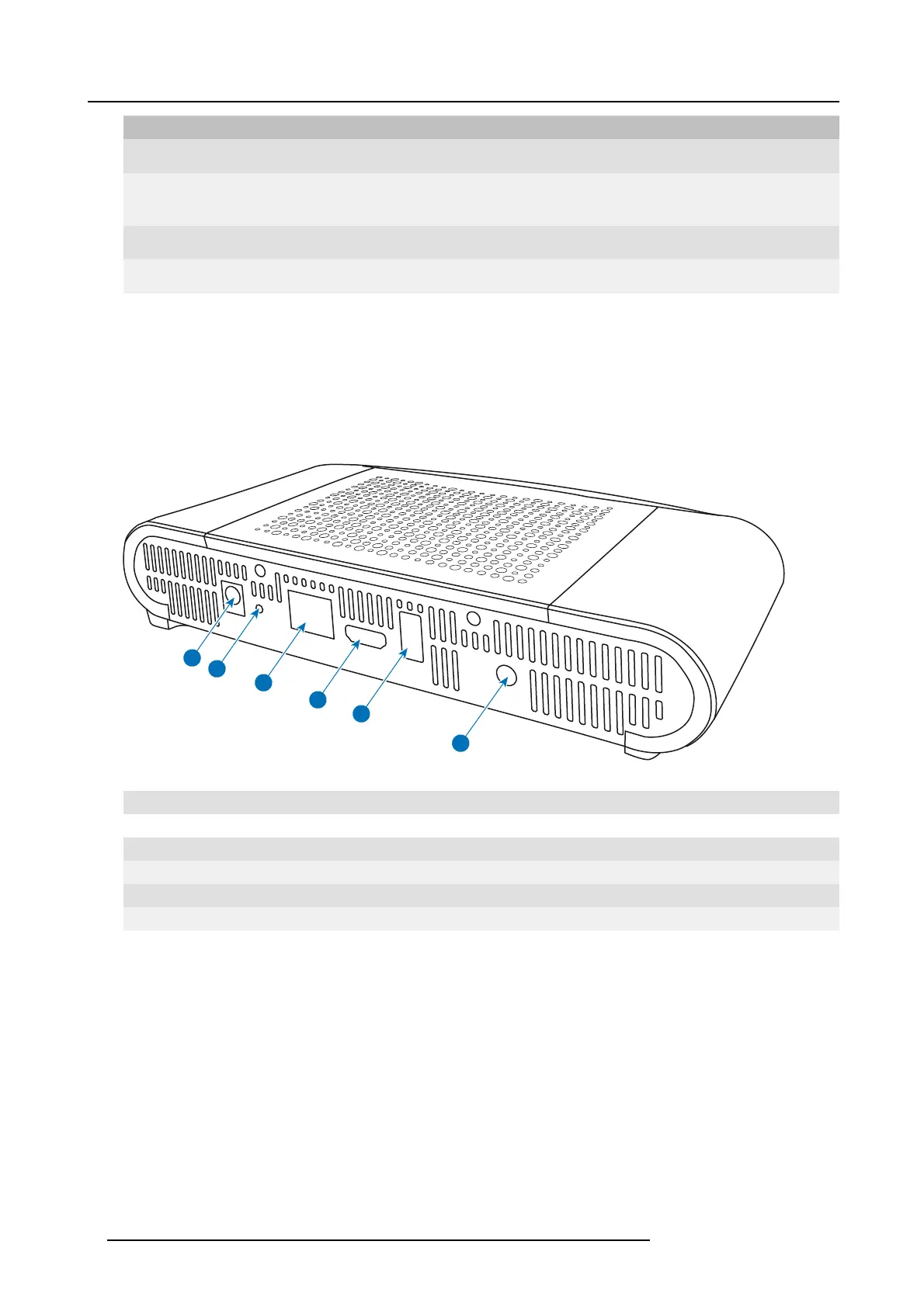
Back layout of the Base Unit
The connection panel is situated at the back of the Base unit.
1
2
3
4
5
6
Image 2-3
Backside Base un it
1 Power connection
2 Reset button
3 LAN Ethernet c onnection
4 HDMI connector
5
USB port
6 Audio out port
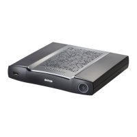
Mechanical fixture points
The mechanical fixture points are loc ated at the bottom of the Base Unit
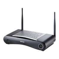
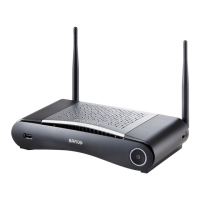
Antenna
The antenna is built-in in the C
S-100.
Bottom layout of the Base Unit
The serial number label containing the Barco part num ber, the revision number, production date (week-year) and the s erial number.
The product label with the applicable certification logos .
8 R5900022 CS-100 16/02/2016