4. CS-100 Installation
6,5
(2x)
161,84
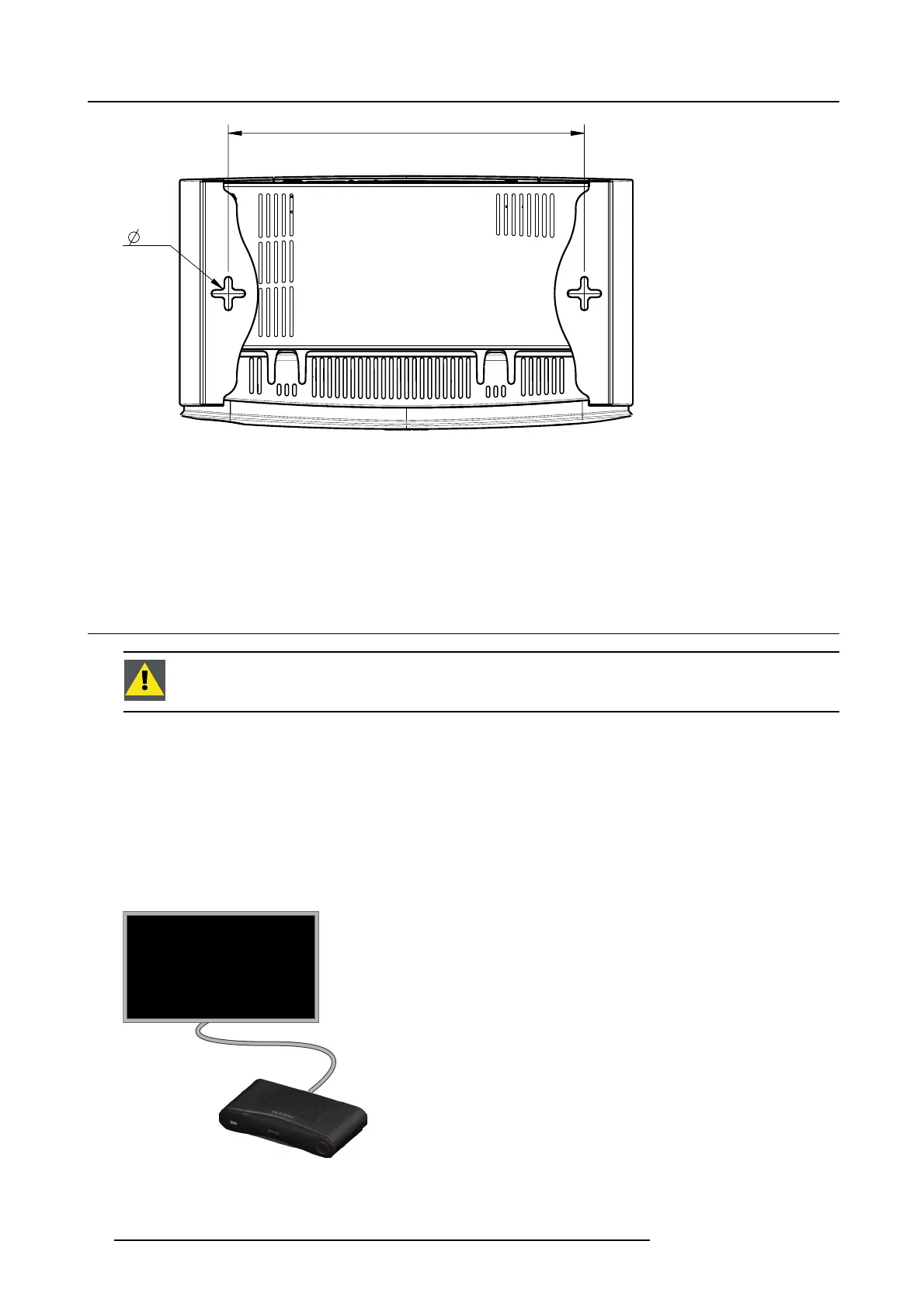
Image 4-1
Mounting holes
2. Insert a plug in eac h hole (if ne eded, depends on the wall or c eiling type) and drive in 2 s crews. Do not drive in the screws
completely.
Note: Mounting screws and plugs are not included in the C S-100 box . The type of screws and plugs depen d on the type of
wall (stone, wood, plasterboard, ...) you are m ounting the Base Unit to. Make sure the head of the screw is not larger
than the hole in the bottom plate of the Base U nit (< 6.5 mm).
3. Hook the Base Unit on both screw heads and slide the Ba se Unit downwards un til it is fixed.
4.4 Video signal connections to the Base unit
CAUTION: Make sure t he Base Unit is installed properly before connecting.
About Video signal connection
A single screen c an be connected to the Base unit.
To connect a display, an H DMI connection should be made between the Base Unit and the display.
To connect
1. Connect the Base unit to the display using a display cable.
Note: No display cables are included in the Click Share box at purchase.
Whe n s etting up a display configuration , connect the HDMI cab le to the display. When necessary, use an adapter piece to c onnect
to a display port or a DVI port o n the display side
.
HDMI
Image 4-2
Display connection
14 R5900022 CS-100 16/02/2016