Camera Interface
BASLER A202k 2-1
DRAFT
2 Camera Interface
2.1 Connections
2.1.1 General Description
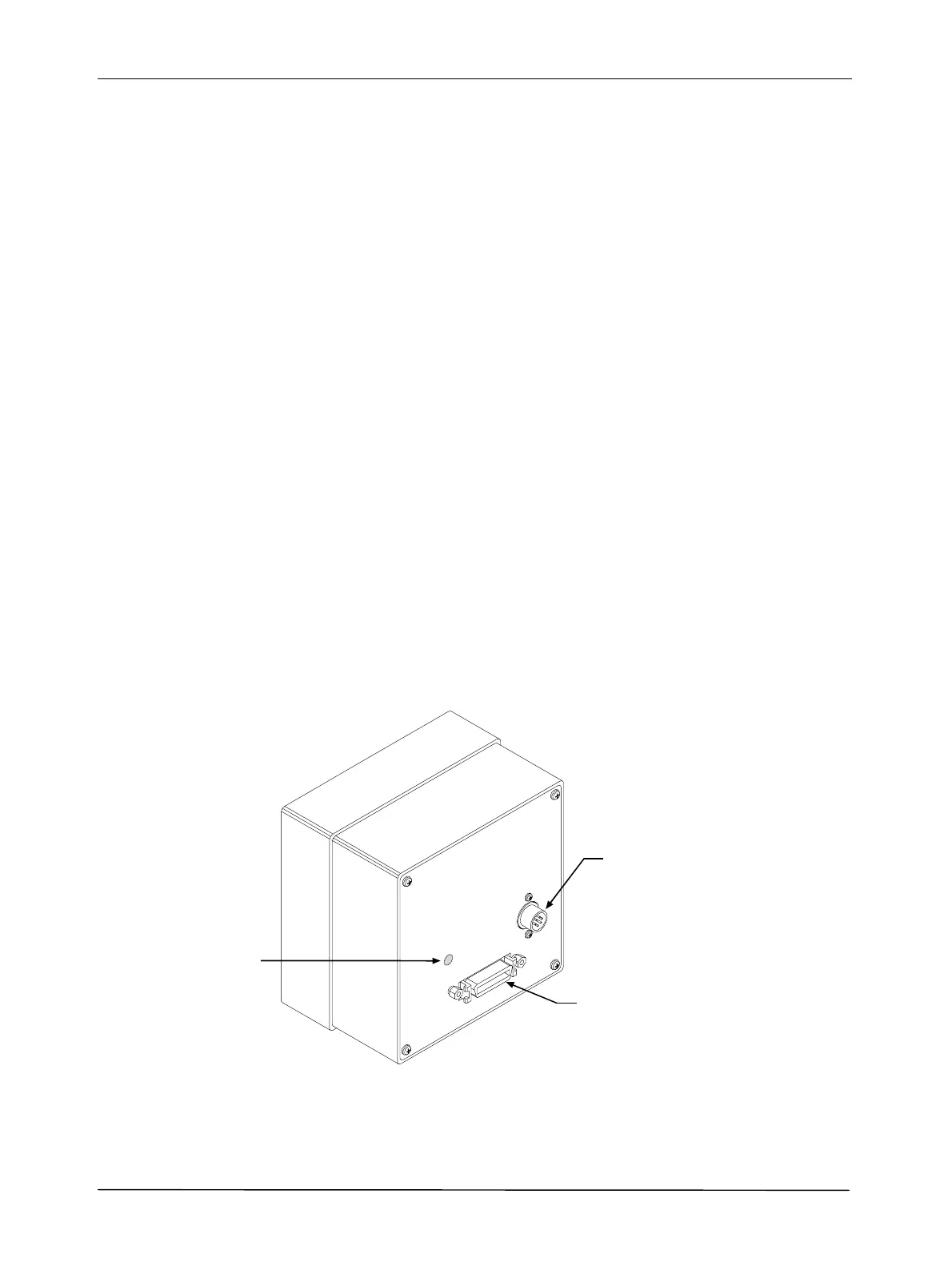
The A202k is interfaced to external circuitry via two connectors located on the back of the camera:
• a 26 pin, .050” Mini D Ribbon (MDR) female connector used to transmit video data, control
signals, and configuration commands.
• a 6 pin, micro-miniature, push-pull receptacle used to provide power to the camera.
A status LED located on the back of the camera is used to indicate power present and signal
integrity. Figure 2-1 shows the connectors and the LED.
Figure 2-1:
A202k Connectors and LED
Micro-miniature
6 Pin Receptacle
26 Pin Female
MDR Connector
LED