Camera Interface
BASLER A202k 2-3
DRAFT
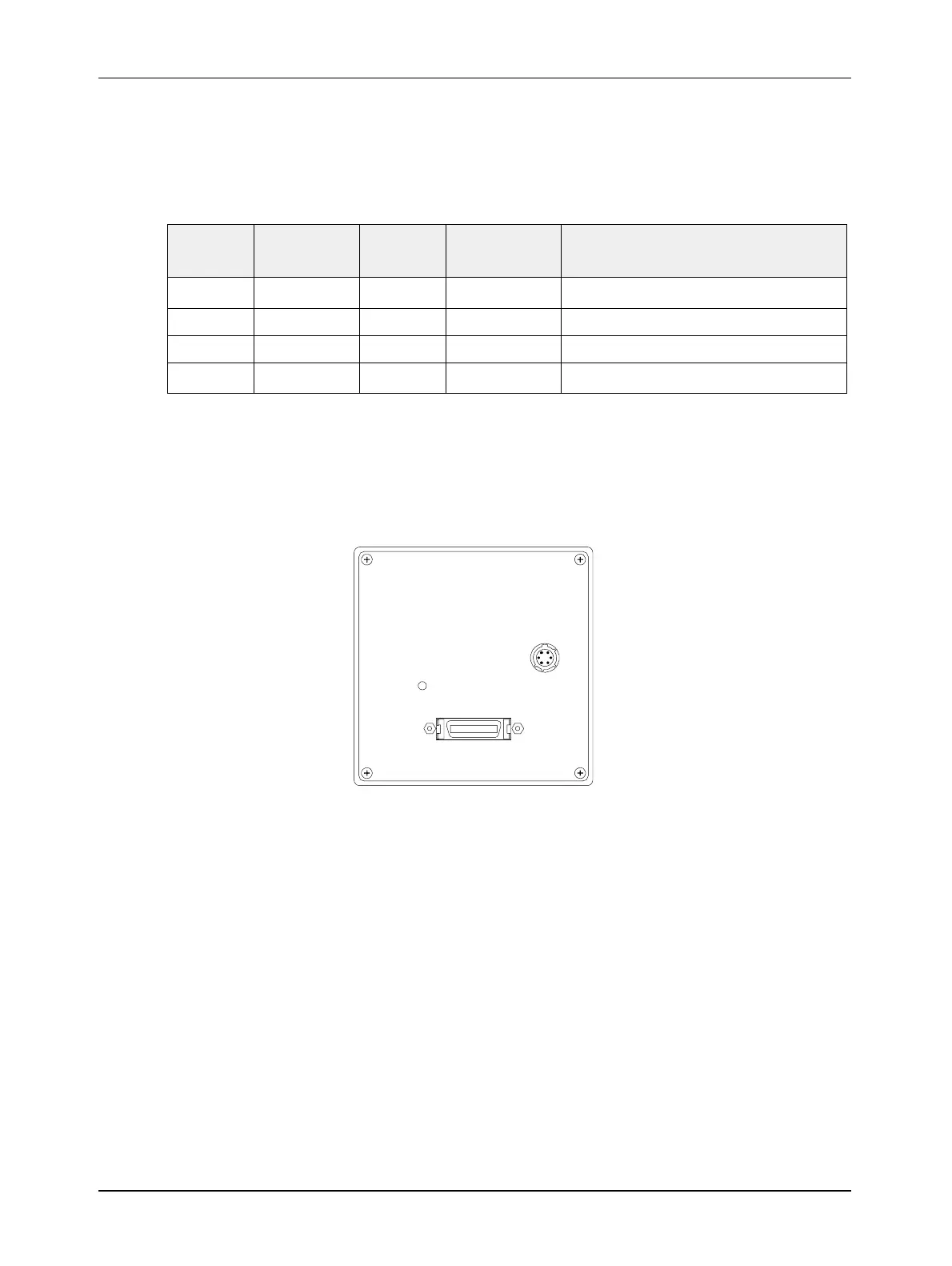
6-Pin Micro-miniature Receptacle
The pin assignments for the 6 pin, micro-miniature receptacle used to supply power to the camera
are shown in Table 2-2.
Figure 2-2:
A202k Pin Numbering
2.1.3 Connector Types
The 26 pin connector on the camera will be a female .050” MDR connector as called for in the
Camera Link Specification.
The 6 pin connector on the camera will be a Hirose micro-miniature locking receptacle (part #
HR10-7R-6PA) or the equivalent. The recommended mating connector is the Hirose micro-
miniature locking plug (part # HR10-7P-6S). A Hirose locking plug will be shipped with each
camera. This plug should be used to terminate the cable on the power supply for the camera. For
proper EMI protection, the power supply cable attached to this plug must be a twin-cored, shielded
cable. Also, the housing of the Hirose plug must be connected to the cable shield and the cable
shield must be connected to earth ground at the power supply.
Pin
Number
Signal
Name
Direction Level Function
1, 2
[1]
12 V In Input +12 VDC Camera Power Input
3
Not Connected
4
Not Connected
5, 6
[2]
DC Gnd
Input Ground DC Ground
[1]
Pins 1 and 2 are tied together inside of the camera.
[2]
Pins 5 and 6 are tied together inside of the camera.
Table 2-2: A202k Pin Assignments for the 6-pin Micro-miniature Receptacle
34
1
2
5
6
1
13
14
26