Operation and Features
BASLER A202k 3-13
DRAFT
3.5 Gain and Offset
The major components in the A202k electronics
include: a CCD sensor, two VGCs (Variable Gain
Controls), and two ADCs (Analog to Digital
Converters). The pixels in the CCD sensor output
voltage signals when they are exposed to light. These
voltages are amplified by the VGCs and transferred to
the ADCs which convert the voltages to digital output
signals.
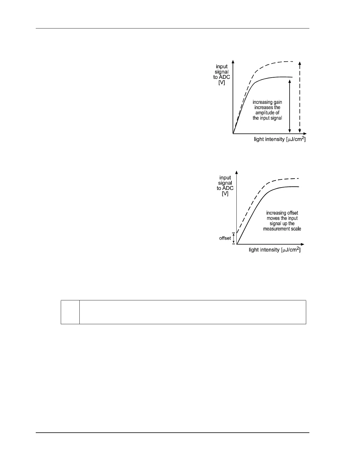
Two parameters, gain and offset are associated with
each VGC. As shown in Figures 3-9 and 3-10,
increasing or decreasing the gain increases or
decreases the amplitude of the signal that is input to
the ADC. Increasing or decreasing the offset moves the
signal up or down the measurement scale but does not
change the signal amplitude.
For most applications, black should have a gray value
of 1 and white should have a gray value of 254 (in 8 bit
output mode) or 1022 (in 10 bit output mode). Attempt
to achieve this by varying exposure and illumination
rather than changing the camera’s gain. The default
gain is the optimal operating point (minimum noise) and
should be used if possible.
Internally, the
A202k processes the left side and the
right side of each image separately in two different data
channels (see Figure 3-1). Consequently, gain must be
adjusted separately for the left side and the right side.
Due to variations in the camera's electronics, the gain
needed on the left side channel to correctly map the
output from the VGC to the input of the ADC may be
different from the gain needed on the right side
channel. Gain balance between the left side and right side channels is important to maintain
uniform output data with minimal gray value differences between the left and right side of the
image. See Section 3.5.2 for more detailed information on balancing the gain.
You can set the gain and offset using either the Camera Configuration Tool (see Section 4.1 and
the configuration tool’s on-line help) or binary commands (see Section 4.2). With the Camera
Configuration Tool, you use the slide controls on the Gain and Offset Tab to easily adjust gain and
offset.
With binary commands, you must use the Left Side Gain and Right Side Gain binary commands
to set the gain and the Left Side Offset and Right Side Offset binary commands to set the offset.
Because increasing gain increases both signal and noise, the signal to noise ratio does
not change significantly when gain is increased.
Figure 3-9: Gain
Figure 3-10: Offset