Camera Interface
2-2 BASLER A202k
DRAFT
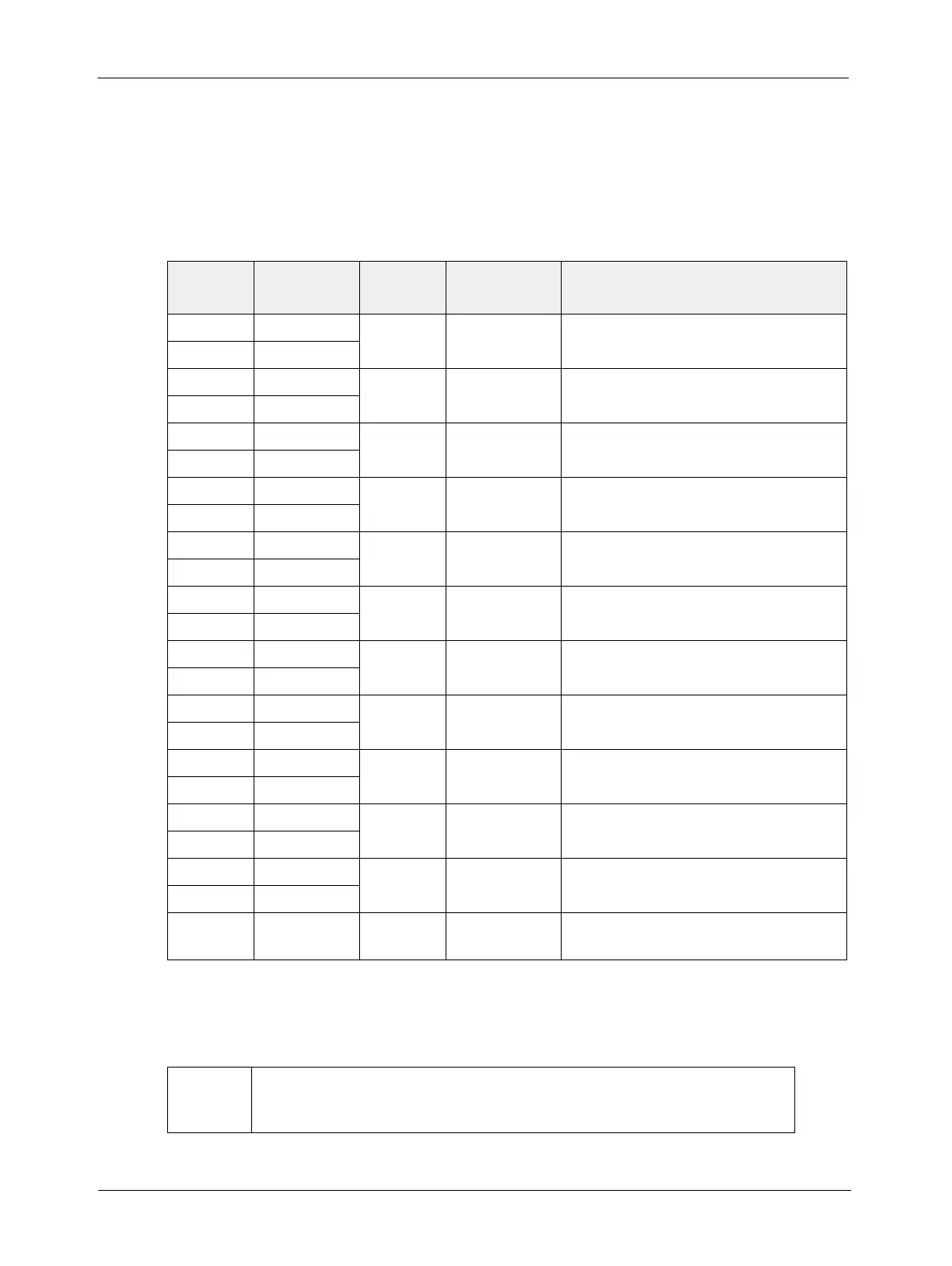
2.1.2 Pin Assignments
26-Pin MDR Connector
The pin assignments for the 26 pin, MDR connector used to transmit video data, control signals,
and configuration commands are shown in Table 2-1.
Pin
Number
Signal
Name
Direction Level Function
15 Tx X0+ Output Camera Link
LVDS
Data from Camera Link Transmitter
2 Tx X0-
16 Tx X1+
Output Camera Link
LVDS
Data from Camera Link Transmitter
3 Tx X1-
17 Tx X2+
Output Camera Link
LVDS
Data from Camera Link Transmitter
4 Tx X2-
19 Tx X3+
Output Camera Link
LVDS
Data from Camera Link Transmitter
6 Tx X3-
18
Tx Clk+ Output Camera Link
LVDS
Clock from Camera Link Transmitter
5
Tx Clk-
12
CC4+ Input RS-644
LVDS
Reserved for Future Use
25
CC4-
24 CC3+ Output RS-644
LVDS
Integrate Enabled
11
CC3-
10 CC2+ Input RS-644
LVDS
Reserved for Future Use
23
CC2-
22 CC1+ Input RS-644
LVDS
External Trigger
9
CC1-
21 SerTFG+ Output RS-644
LVDS
Serial Communication Data Transmit
8
SerTFG-
7 SerTC+ Input RS-644
LVDS
Serial Communication Data Receive
20
SerTC-
1, 13,
14, 26
[1]
DC Gnd
Input Ground DC Ground
[1]
Pins 1, 13, 14, and 26 are all tied together inside of the camera.
Table 2-1: A202k Pin Assignments for the 26-pin MDR Connector
The camera housing is not grounded and is electrically isolated from the cir-
cuit boards inside of the camera.