A: PL120100.056
B: PL120100.056
E: 03.93 / T. Weiß
G: 06.93 / T. Weiß
Chapter: 5.6
Page: 3
?
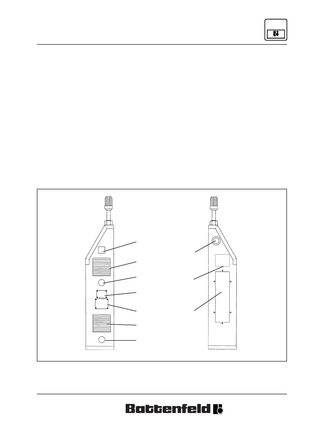
Structure and Function
Right-hand view of control box:
1) Combined cycle counter and time meter
2) Outlet filter
3) Inlet filter
4) Main input point, top
5) Main input point, bottom
6) Type plate
7) Rating plate
Left-hand view of control box:
1) EMERGENCY STOP button
2) Socket holding plate
3) Device for switching to follow-up pressure,
depending
on the pressure inside the mould (optional)
Bild: Pl-0023.TIF
Bild: Pl-0024.DRW
1
2
3
1
2
4
6
7
5
2