Oceanus
Page 8 2nd Edition, Rev. 0 Chg. 14
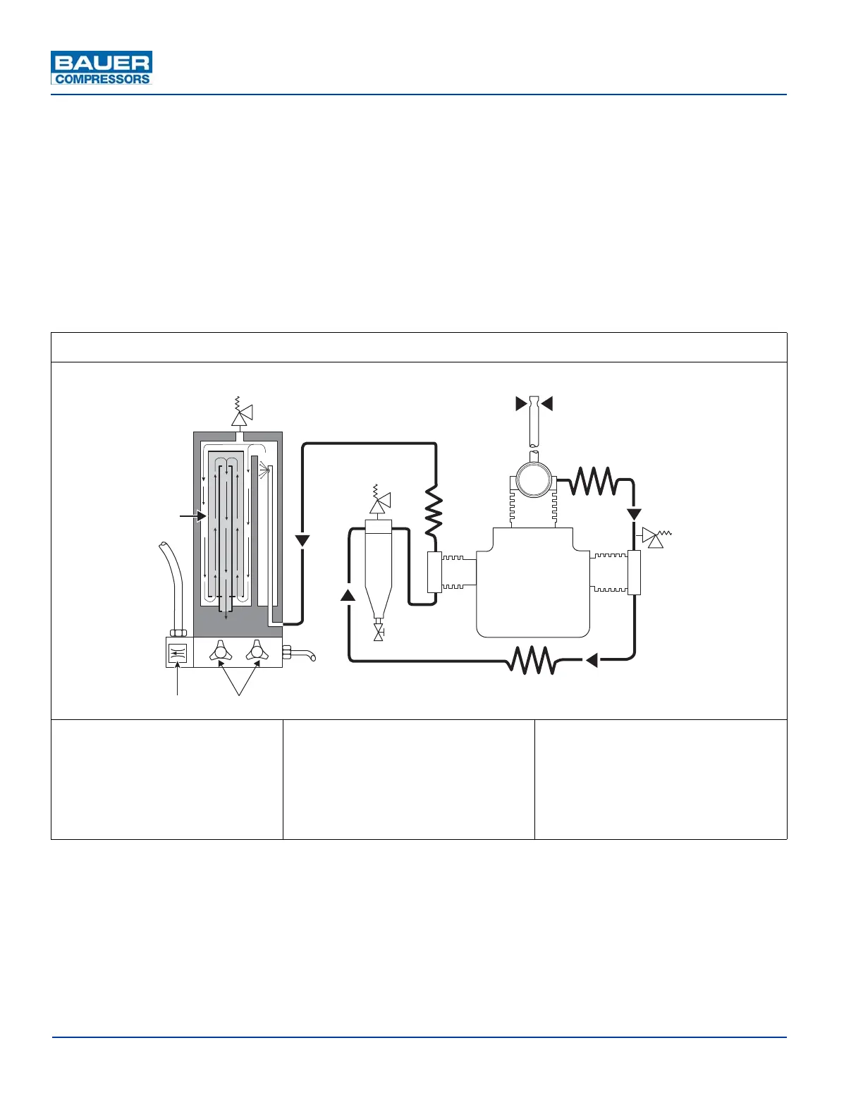
1.4.3 Air Flow Diagram
See Figure 1-7. On units with a gasoline engine drive the air is drawn in through the Telescopic Tube
(1) which moves the intake air source away from the engine exhaust. On all units the intake air goes
through the Intake Filter (2) and is compressed to final pressure in the Cylinders (3, 4 and 5). It is
cooled by the Intercoolers (6 and 7) and the Aftercooler (9). The pressure of the individual stages is
controlled by Safety Valves (10 and 11). The compressed air is cleaned in the Intermediate Separator
(8) and purified in the P0 Filter System (13). The Intermediate Separator and P0 Filter System are
drained by the Condensate Drain Valves (15). The Pressure Maintaining Valve (16) provides a constant
pressure within the P0 Filter System. The purified compressed air then passes through the Fill Hose
(17) and Fill Valve (18) to the bottles to be filled. Fill pressure is indicated by the Final Pressure Gauge
(19).The Final Safety Valve (12) is adjusted to blow off at the pressure selected.
Figure 1-7 Internal Air Flow Diagram
1. Telescopic Air Intake
2. Intake Filter
3. 1st Stage Cylinder
4. 2nd Stage Cylinder
5. 3rd Stage Cylinder
6. 1st/2nd Stage Intercooler
7. 2nd/3rd Stage Intercooler
8. Intermediate Separator
9. After Cooler
10. 1st Stage Safety Valve
11. 2nd Stage Safety Valve
12. Final Pressure Safety Valve
13. P0 Filter System
14. Triplex
®
Cartridge
15. Condensate Drain Valve
16. Pressure Maintaining Valve
17. Fill Hose
17
13
14
15
12
11
8
15
9
5
2
3
4
6
10
7
1
16