MNL-0295
August 27, 2009 Page vi
List of Figures
CHAPTER 1: - - - - - - - - - - - - - - - - - - - - - INTRODUCTION
Figure 1-1 Compressor Identification Plate ..............................................................................................................................2
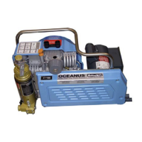
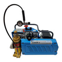
Figure 1-2 Oceanus with Gasoline Engine (typical).................................................................................................................4
Figure 1-3 Oceanus GS; Belt Side ............................................................................................................................................5
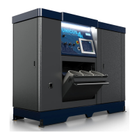
Figure 1-4 Oceanus with Three Phase Electric Motor..............................................................................................................6
Figure 1-5 Oceanus with Single Phase Electric Motor .............................................................................................................6
Figure 1-6 Oceanus, V-belt Pulley Side....................................................................................................................................7
Figure 1-7 Internal Air Flow Diagram......................................................................................................................................8
CHAPTER 2: - - - - - - - - - - - - - - - - - - - - - - - OPERATION
Figure 2-1 Air Storage Bottle Valve Operating Sequence......................................................................................................15
CHAPTER 3: - - - - - - - - - - - OCEANUS COMPRESSOR BLOCK
Figure 3-1 Oil Dipstick Markings ...........................................................................................................................................17
Figure 3-2 Intake Filter ...........................................................................................................................................................18
Figure 3-3 Intermediate Separator...........................................................................................................................................19
Figure 3-4 Valve Function ......................................................................................................................................................20
Figure 3-5 1st Stage Plate Valve.............................................................................................................................................20
Figure 3-6 1st Stage Valve Head.............................................................................................................................................22
Figure 3-7 2nd Stage Valve Head ...........................................................................................................................................23
Figure 3-8 3rd Stage Valve Head............................................................................................................................................24
Figure 3-9 Removing the 3rd Stage Valves ............................................................................................................................25
Figure 3-10 Crankcase, Driving Gear and Fanwheel................................................................................................................30
Figure 3-11 Pistons and Cylinders ............................................................................................................................................32
Figure 3-12 Valve Heads and Valves........................................................................................................................................34
Figure 3-13 Cooling System .....................................................................................................................................................36
Figure 3-14 Intake Filter and Intermediate Separator...............................................................................................................38
Figure 3-15 Frame with Accessories.........................................................................................................................................40
Figure 3-16 Oceanus-G Gasoline Engine..................................................................................................................................42
Figure 3-17 Oceanus -E1 Electric Motor..................................................................................................................................43
Figure 3-18 Oceanus -E3 Electric Motor..................................................................................................................................44
Figure 3-19 Special Tools .........................................................................................................................................................45
Figure 3-20 Manual Drains .......................................................................................................................................................46
CHAPTER 4: - - - - - - - - OCEANUS MAINTENANCE SCHEDULE
There are no Figures in this Chapter
CHAPTER 5: - - - - - - - - - - - - - - - - PURIFICATION SYSTEM
Figure 5-1 Cartridge Safety Venting.......................................................................................................................................51
Figure 5-2 Purification Dataplates (typical)............................................................................................................................52