EasyManua.ls Logo

Bauer BG 25 - Stability for BG 25 # 2254 - Kelly BK 25;394;4;40; Load Capacity Chart

Bauer BG 25
183 pages
To Next Page IconTo Next Page
To Previous Page IconTo Previous Page
Loading...
SAFETY
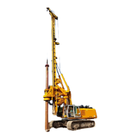
BG 25 / 2011 / 2254_BG25_en_0000498763_V01
2 - 9
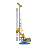
2.5.3 Stability for BG 25 # 2254 - Kelly BK 25/394/4/40
2.5.3.1 Load Capacity Chart
Valid only for
Mast extension --- m
--- t
Counterweight
6.20 + 6.20 t
Kelly BK 25/394/4/40
7.70 t
Casing drive adapter 1,500 mm
1.90 t
Drilling tool 1,350 mm
2.30 t
Conditions for operation
Crowd sledge stopper mounted (max. stroke: 8,120 mm)
B0000689.wmf
B00005003.wmf
B00005002.wmf
Max permissible load / max ground pressure**
Min. drilling distance*: -- m
Max. drilling distance*: 3.39 m
Auxiliary
rope
8.0 t
390 kPa
Main rope
20.0 t
370 kPa
Crowd
26.0 t
420 kPa
Auxiliary
rope







120°
8.0 t
690 kPa
Main rope







120°
20.0 t
490 kPa
Crowd







120°
26.0 t
570 kPa
Auxiliary
rope






5.0 t
560 kPa
Main rope






20.0 t
490 kPa
Crowd






26.0 t
570 kPa
Max. working platform inclination /
max. ground pressure ***
5° / 310 kPa
*) Drilling distance = centre distance from machine to drilling tool
**) Max. value of ground pressure as calculated in conformance with DIN EN 791 (1995 issue)

Table of Contents

Related product manuals