25
Filter pump control
User Manual PoolManager
®
59
The following settings are available:
Menu Filter pump
Filter pump mode of operation
Selection of operating mode:
• Inactive (Filter pump control not used)
• Filter pump off
• Normal operation
• Reduced output
• Increased output
• Timer
Programmable timer
Programming timers.
Basic configuration
Basic settings for filter pump control.
Dosing settings
Determine dosing behaviour for different filter pump operation modes.
Safety settings
Security settings for filter pump control.
INFO
Allocation of relay switch outputs
An
operating mode can only be activated if you have
allocated a relay switch output to it beforehand.
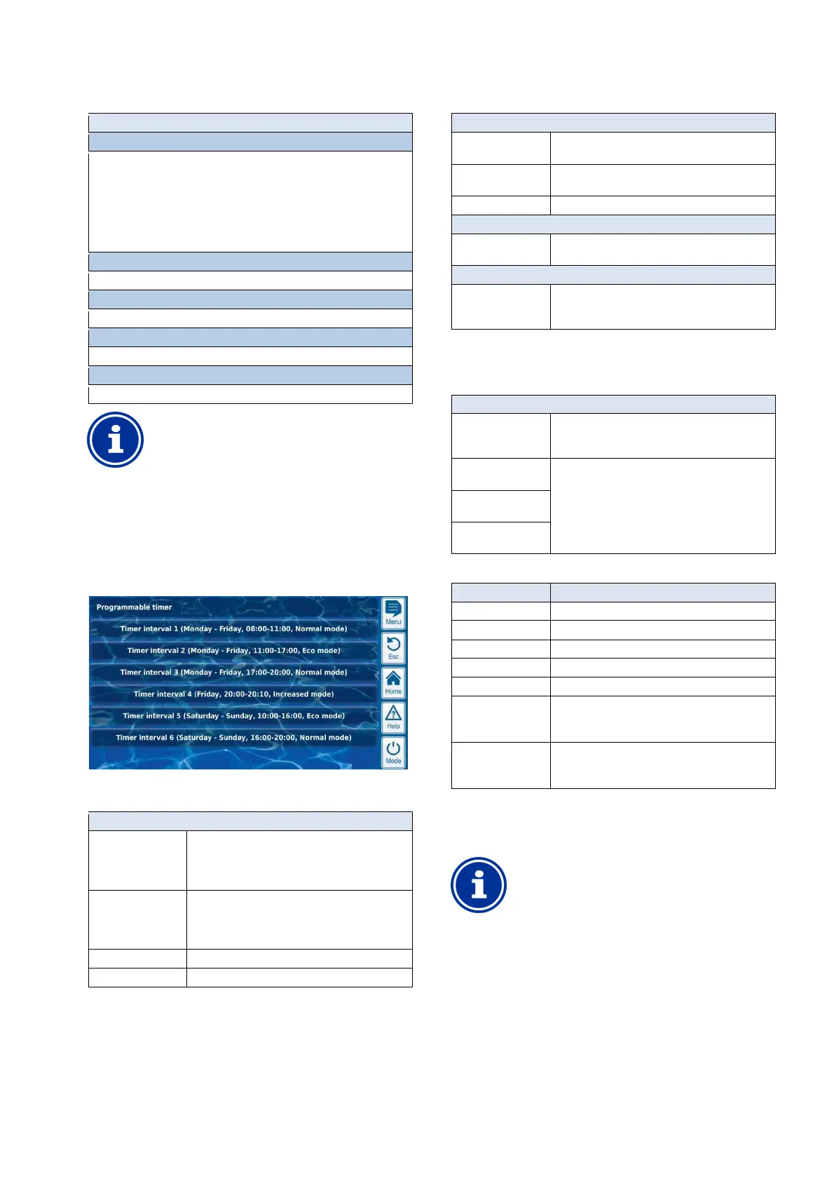
25.3.1 Programmable timer
This menu provides 6 programmable time intervals for filter pump
control.
The time intervals are displayed in the menu in an easy-to-follow
manner with programmed weekdays and times and with the filter
pump's operating mode:
The following settings are possible for each of the 6 time intervals:
Sub-menu Timer interval (1..6)
Filter pump operating
mode
The desired operating mode for this time interval:
• Normal operation
• Reduced output
• Increased output
Days of week Selection of one or multiple weekdays on which the
time interval should be active.
If no weekday is activated, then the entire time
interval is inactive.
Switch-on time Time at which switch-on occurs.
Switch-off time Time at which switch-off occurs
25.3.2 Basic configuration
The menu Basic configuration is used to configure the basic settings
for a switch output. This is generally done once upon placing into
operation.
The following settings are available:
Sub-menu Basic configuration
Filter pump control
interface
Relay trigger or
4x power output 0/4-20mA
Allocation of inputs
and outputs
See universal switch output.
Dosage blocking See Dosing settings
For Relay trigger only
Allocation of
inputs and outputs
See Allocation of inputs and outputs.
Only for power output 0/4-20mA
Configuration power
output
0/4-20mA
See Configuration power output
0/4-20mA.
25.3.2.1 Allocation of inputs and outputs
For Relay trigger only.
This menu allocates the relay switch outputs for filter pump control.
Sub-menu Allocation of inputs and outputs
Relay output 'Filter
pump on/off'
Relay switch output for turning on the filter pump (for
conventional filter pumps or as superordinate on/off
switch for variable filter pumps).
Relay output 'normal
mode'
Relay switch outputs for activating the various
operating modes for variable filter pumps.
Note: Not all three operating modes have to be used.
Relay output
'Eco mode'
Relay output
'Increased output'
For each relay switch output, the following settings are available:
Setting Description
None The corresponding function is not used.
OUT 1 [26] Relay switch output OUT 1 [terminal block 26]
OUT 2 [27] Relay switch output OUT 2 [terminal block 27]
OUT 3 [30] Relay switch output OUT 3 [terminal block 30]
OUT 4 [31] Relay switch output OUT 4 [terminal block 31]
pH+ [22] Dosage relay pH + [terminal block 22]
Can only be used
if no pH+ dosage is used.
pH- [21] Dosage relay pH - [terminal block 21]
Can only be used
if no pH- dosage is used.
25.3.2.2 Configuration power output 0/4-20mA
Only for triggering with Power output 0/4-20mA.
This menu configures the power output for the filter pump control.
INFO
Plug-in module PM5-SA4 needed
To trigger the filter pump via a power output
04/-20mA, the following optional plug-
needed:
PM5-SA4 CONVERTER 0/4-20MA (Art. no. 127011)