48
Hardware description
User Manual PoolManager
®
87
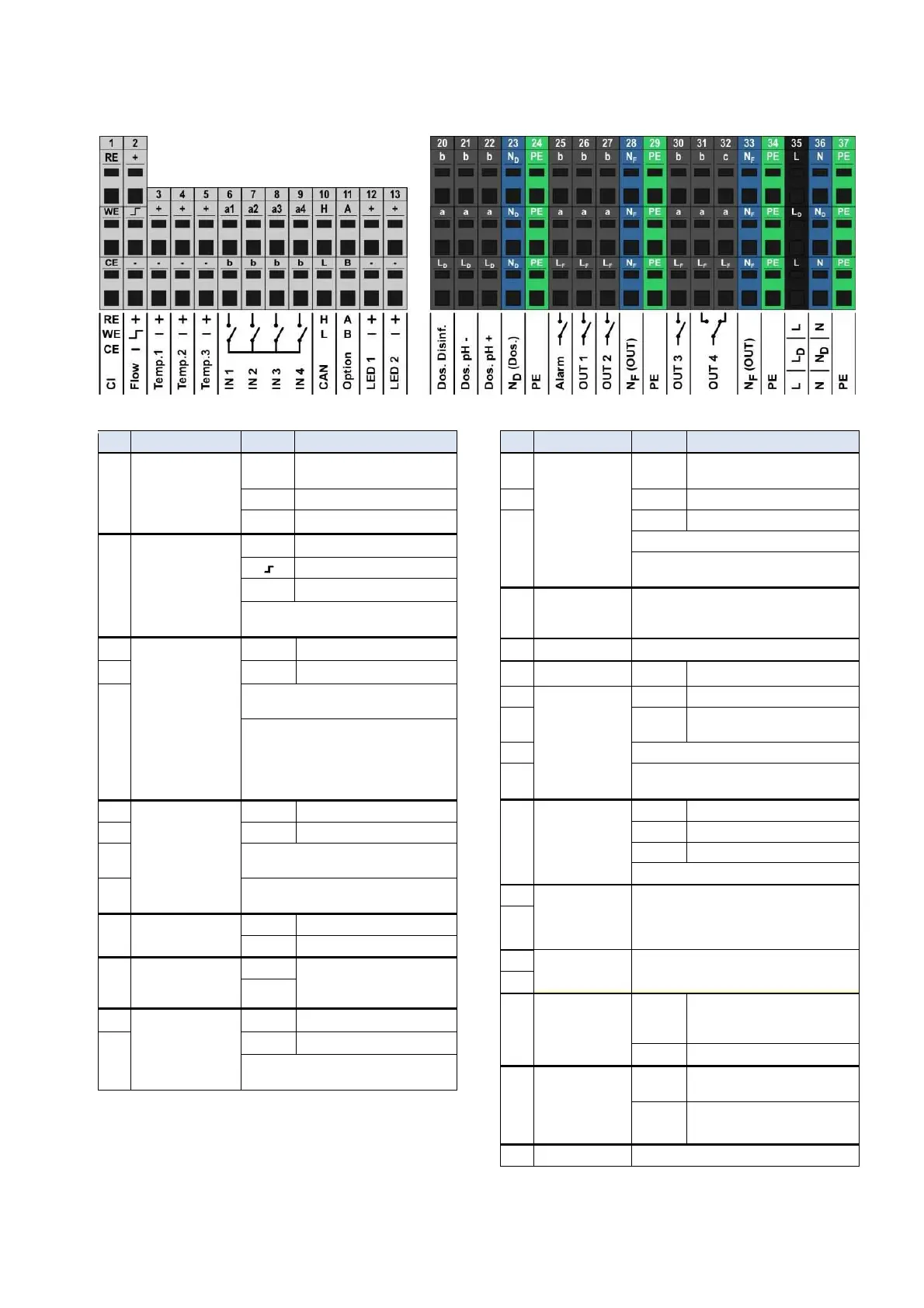
48.4.2 Connection terminals
48.4.2.1 Connection terminals of low voltage
No. Function Terminal Notes
1 Potentiostatic chlorine
measurement
(ANALYT and
PoolManager
®
PRO
only)
RE Reference electrode
(Ag/AgCl)
WE Working electrode (gold)
CE Counter electrode (platinum)
2 Flow switch
(inductive proximity
switch
"OMRON")
+
Supply voltage
Signal output
-
Ground (GND)
During flow, the signal output
is switched to GND
3 Temperature inputs
1 / 2 / 3
+
Measurement input
4
-
Ground (GND)
5 Temp. 1 / 2 0..50°C (820..1200
Ω
)
Temp. 3 0..75°C (820..1400
Ω
)
Sensor types supported:
• PT1000
• KTY83
• KTY16-6
(Parallel resistance 2k
Ω
required!)
6 Universal switch
inputs
IN 1 / IN 2 / IN 3 / IN 4
a1/2/3/4 Signal input
7 b Ground (GND)
8 For connecting potential free external
switches or switch contacts.
9 IN 1 can optionally be used for flow
monitoring.
10 CAN-Bus H CAN High
L CAN Low
11 Option A These terminals are connected
with expansion plugs and
reserved for future functions.
B
12 LED 1 / LED 2
+
5V with 50
Ω
series resistance
13
-
Ground (GND)
For connecting LEDs for lighting effects
(optional)
48.4.2.2 Connection terminals for 230VAC
No. Function Terminal Notes
20 Dosing outputs
• Disinfection
• pH-
• pH+
b Relay working contact
(Dosing output)
21 a Relay centre contact
22 L
D
Phase 230V~ for dosing outputs
Potential free switch contact between a and b.
Wiring bridge from L
D
to a
230V~ on working contact b
23 Neutral conductor
N
D
for dosing
outputs
Neutral conductor N
D
is not internally connected
with neutral conductors N
F
and N!
24 Protective earth PE
All PE terminals are connected internally
25 Alarm relay b Relay working contact
26 Relay switch
outputs for
supplemental
functions
OUT 1 / OUT 2 /
OUT 3 / OUT 4
a Relay centre contact
27 L
F
Phase 230V~ for alarm relay
and supplemental functions
30 Potential free switch contact between a and b.
31 Wiring bridge from L
F
to a
230V~ on working contact b
32 Relay switch output
OUT 4
Resting contact
c Relay resting contact
a Relay centre contact
L
F
Phase 230V~
1
OUT 4 inactive Contact a-c closed
28 Neutral conductor
N
F
for alarm relay
and supplemental
functions
Neutral conductor N
F
is internally connected
with neutral conductor N, but not with neutral
conductor N
D
!
33
29 Protective earth PE
All PE terminals are connected internally
34
35 Input phase
230V~
L
(also L
F
)
PoolManager
®
supply, alarm relay,
and supplemental functions
(L
F
fused with 4AT)
L
D
Supply dosing outputs
36 Input neutral
conductor
230V~
N
(also N
F
)
PoolManager
®
supply, alarm relay,
and supplemental functions
N
D
Supply dosing outputs
37 Protective earth PE
All PE terminals are connected internally