26
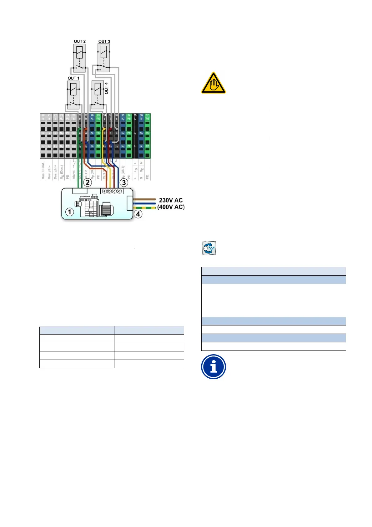
Flockmatic pump
1 Filter pump
2 Potential free control input on/off
3
Potential free control input for operating mode
3a
Potential free control input for normal operation
3b
Potential free control input for reduced output
3c
potential free control input for increased output
3d
Joint contact for all
potential free control inputs
4
External power supply for the filter pump
(or 400V~)
The following
Allocation of inputs and outputs
for the connection schematic shown in the figure:
Function
Relay output 'Filter pump on/off'
Relay output 'normal operation'
Relay output 'reduced output'
Relay output increased output'
User Manual PoolManager
®
Potential free control input for operating mode
Potential free control input for normal operation
Potential free control input for reduced output
potential free control input for increased output
External power supply for the filter pump
230V~
Allocation of inputs and outputs
is required in the menu
for the connection schematic shown in the figure:
OUT 1 [26]
OUT 2 [27]
OUT 3 [30]
OUT 4 [31]
26 Flockmatic pump
26.1 Safety information
Requisite user qualification:
TRAINED
Connection, configuration, and start
control may only be performed by a TRAINED
SPECIALIST or an ELECTRICAL SPECIALIST as
26.2 Overview
PoolManager
®
offers the option of connecting and controlling a
Flockmatic pump.
PoolManager
®
Flockmatic control additionally offers the following
options:
•
Reducing Flockmatic dosing output
•
Blocking flock dosing in the event of missing flow
• Flexible allocation of up to
three relay switch outputs for the filter
pump's various operating modes
•
Multiple flexibly programmable timers
•
Optional level monitoring via a switch input
26.3 Menu
The configuration menu for Flockmatic control is called up with the
following icon:
Flockmatic pump
The following settings are available:
Menu Flockmatic pump
Flockmatic mode of operation
Selection of operating mode:
•
Inactive (Flockmatic control not used)
•
Off (Flockmatic used, but turned off)
• On
• Timer
Programmable timer
Programming timers.
Basic configuration
Basic settings for Flockmatic control.
INFO
Allocation of a relay switch output
Flockmatic control can only be activated if you have
allocated a relay switch output to it beforehand.
26.3.1 P
This menu provides 3 freely programmable time intervals
for Flockmatic control.
Programming here is identical to programming the timers for the
universal switch outputs, see
Universal switch outputs,
programmable timer.
26.3.2
The menu Basic configuration
is used to configure the basic settings
for Flockmatic control. This is generally done once upon placing into
operation.
61
Requisite user qualification:
Connection, configuration, and start
-
control may only be performed by a TRAINED
SPECIALIST or an ELECTRICAL SPECIALIST as
User qualification.
offers the option of connecting and controlling a
Flockmatic control additionally offers the following
Reducing Flockmatic dosing output
Blocking flock dosing in the event of missing flow
three relay switch outputs for the filter
pump's various operating modes
Multiple flexibly programmable timers
Optional level monitoring via a switch input
The configuration menu for Flockmatic control is called up with the
The following settings are available:
Inactive (Flockmatic control not used)
Off (Flockmatic used, but turned off)
Basic settings for Flockmatic control.
Allocation of a relay switch output
Flockmatic control can only be activated if you have
allocated a relay switch output to it beforehand.
This menu provides 3 freely programmable time intervals
Programming here is identical to programming the timers for the
Universal switch outputs,
freely
is used to configure the basic settings
for Flockmatic control. This is generally done once upon placing into