Page10
CABLING
RJ45Cable
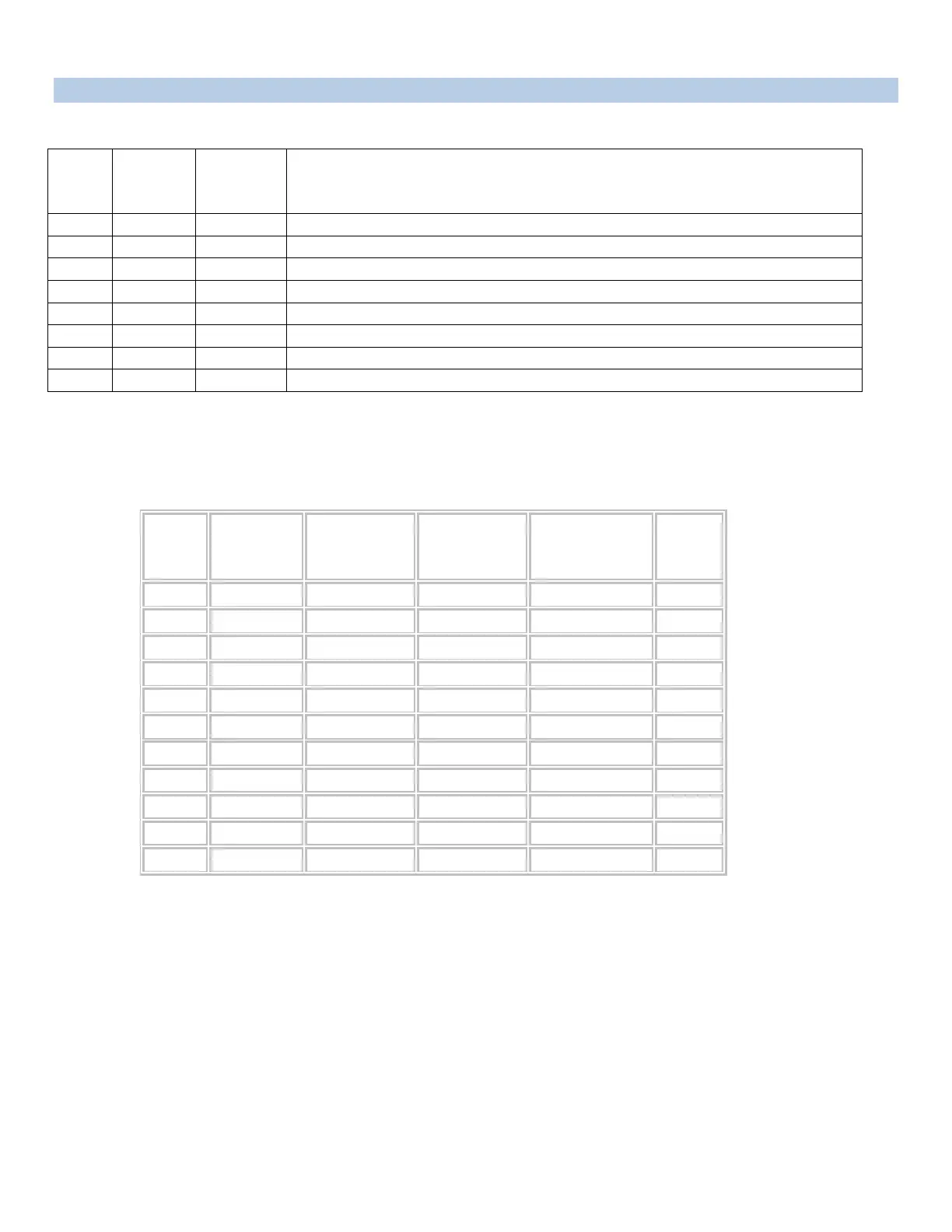
Control Module RJ-45 pin Signals
Pin
EIA
232
Signal
Signal
Directio
n
Description
1 DTR Out +10V when activated by DCD. Toggles on logout for modem disconnect.
2 GND Signal Ground
3 RTS Out +10 V when power is applied. Not used as a handshake line.
4 TX Out Transmit (Data Out)
5 RX In Receive (Data In)
6 N/C In No Connection.
7 GND Signal Ground
8 DCD In DCD into the MMP.
Adapter signals
Listed are the pin specifications for the BayTech cable and adapters and the terminal COM ports:
Serial 1: Port Pin Out Table
Signal RS-232
Port (DS)
RS-232
Port
(MMP)
COM Port
DE-9 Pin
COM Port
DB-25 Pin
Signal
DTR 1 1 4 20 DSR
GND 2 2 1 GND
RTS 3 3 7 5 CTS
TXD 4 4 3 2 RXD
RXD 5 5 2 3 TXD
DSR 6 N/C 6 6 DTR
GND 7 7 5 7 GND
CTS 8 8 4 RTS
DTR 4 DCD
DCD 8 1 8 DTR
RI 9 22