This page is displayed only if
the DIMMING Input is either
selected for “14V or 28V” dim-
bus voltage.
(see Installation Setup page
“DIMMING Input”)
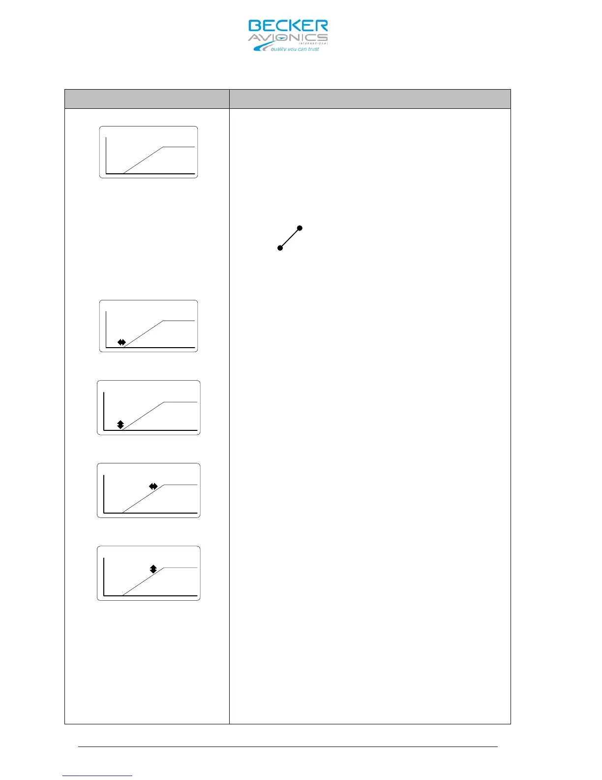
Provision for adjustment of the illumination
curve
(relation between dimming bus voltage and
brightness of the LCD and push-button
illumination)
on the following four points.
Use the “ROTARY ENCODER” for adjustments and a
push on “STO” button toggles between the 4
adjustment points.
voltage V2
voltage V1
(1) This adjustment defines where the
brightness increase will start.
(between 0 volt and V1 the brightness is zero, the
lowest trigger point for V1 can be adjusted to
≈1.5
Volts for a 14 volt dimming bus and to ≈ 4 Volts for
a 28 Volt dimming bus).
(2) With this adjustment is defined the value
of brightness increase when the trigger point of
V1 is reached.
(3) With this adjustment is defined the rate of
brightness increase starting at the trigger
point of V1 until V2 is reached.
(4) This adjustment is setting the point of
the max possible brightness related to a
certain value of the dimming voltage from where
the brightness is no more increasing even when
the dimming voltage can go up further.