AR6201 - RT6201 - RCU6201 - AR6203
DV 14307.03 Issue 1 09/2013 Page 2-3
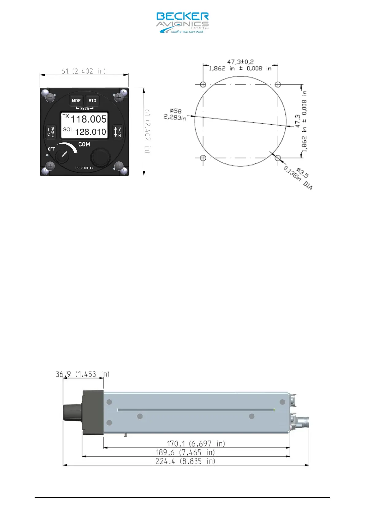
Figure 2-3: AR6201 and RCU6201
front view, dimensions in mm and
(inches)
Figure 2-4: Drilling jig for back-panel mounting;
dimensions in mm and (inches)
2.3.2 AR6203 Installation
The AR6203 is designed to be mounted in the aircraft instrument panel within
easy view and reach of pilot/operator. The mounting location for AR6203 shall
be at least 30 cm away from the aircraft magnetic compass, to avoid any
interference to the magnetic compass by the transceiver. For unit dimensions
refer to Figure 2-5 and Figure 2-6. Leave a clearance of minimum 5 mm between
the AR6203 and other avionics to allow air circulation. Forced cooling is
usually not required.
For installation of the AR6203 use the designated mounting kit MK6403-1,
dimensions are shown in Figure 2-7.
First secure the mounting kit frame in the aircraft using 6 holes located on
both sides of the frame, marked with “C” letter on figure. Countersunk screws
are included in the delivery. Slide in the VHF transceiver into the mounting
up to the stop. Use a hex-wrench to tightening the AR6203 in the final
position.
Figure 2-5: AR6203 side view, dimensions in mm and (inches)